We use essential cookies to make Venngage work. By clicking “Accept All Cookies”, you agree to the storing of cookies on your device to enhance site navigation, analyze site usage, and assist in our marketing efforts.
Manage Cookies
Cookies and similar technologies collect certain information about how you’re using our website. Some of them are essential, and without them you wouldn’t be able to use Venngage. But others are optional, and you get to choose whether we use them or not.
Strictly Necessary Cookies
These cookies are always on, as they’re essential for making Venngage work, and making it safe. Without these cookies, services you’ve asked for can’t be provided.
Show cookie providers
- Google Login
Functionality Cookies
These cookies help us provide enhanced functionality and personalisation, and remember your settings. They may be set by us or by third party providers.
Performance Cookies
These cookies help us analyze how many people are using Venngage, where they come from and how they're using it. If you opt out of these cookies, we can’t get feedback to make Venngage better for you and all our users.
- Google Analytics
Targeting Cookies
These cookies are set by our advertising partners to track your activity and show you relevant Venngage ads on other sites as you browse the internet.
- Google Tag Manager
- Infographics
- Daily Infographics
- Popular Templates
- Accessibility
- Graphic Design
- Graphs and Charts
- Data Visualization
- Human Resources
- Beginner Guides
Blog Graphic Design 10 Use Case Diagram Examples (and How to Create Them)

10 Use Case Diagram Examples (and How to Create Them)
Written by: Letícia Fonseca Feb 15, 2022

Use case diagrams are a great tool that can help businesses and developers alike to design processes and systems.
By capturing requirements and expectations from a user’s point of view, they ensure the development of correct and efficient systems that will properly serve a user’s goals.
In this article, we will define what a use case diagram is and provide you with different use case diagram examples.
You can create your own use case diagrams using Venngage’s Diagram Maker and use case diagram templates . No design experience is required!
Click to jump ahead:
What is a use case diagram?
- 5 Use case diagram examples and templates that you can use
What are the benefits of a use case diagram?
Types of use case diagrams, what are the elements of a uml use case diagram, faqs about use case diagrams.
A use case diagram is a visual representation of the different ways and possible scenarios of using a system. It illustrates how a user will perform actions and interact with a particular system, such as a website or an app.
For example, this use case diagram depicts the different functions of a banking system for customers:

In Unified Modeling Language (UML), systems are presented at different levels of detail to show a specific perspective in the system’s design. Use case diagrams are considered UML diagrams.
UML diagrams define and organize the high-level functions and scope of a system. By modeling the basic flow of events in a use case, they help identify the goals that you need to achieve with every system-user interaction.
5 Use case diagram examples and templates that you can use:
Here are some use case diagram templates and examples to guide your diagram creation process:
Retail use case diagram
This use case diagram example depicts the internal functions and employee interactions within a retail system.

It features basic system functions represented by color-coordinated boxes to signify use cases based on the user’s role. A use case diagram like this can be of great use to retail stores with B2C e-commerce systems.
Design a use case or UML diagram that reflects your brand with Venngage’s My Brand Kit feature.
Add your website when prompted and the editor automatically imports all your brand assets, including your logo, colors, and fonts.
Restaurant use case diagram
In this example, a restaurant’s daily operations serve as the system, the staff represent the actors, and their tasks are the use cases.
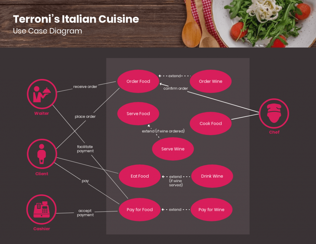
This use case diagram can be particularly helpful to restaurants or fast-food chains in terms of systemizing routine processes and presenting day-to-day activities to employees in a simpler and more orderly way.
Travel use case diagram
Here is a use case diagram that maps out how different types of users can engage with a travel booking website or application.

This comprehensive template includes extended use cases marked by dotted lines and arrows instead of simple lines. It can be scaled down or up for hotels, airlines, and other travel reservation systems.
Banking use case diagram
Designed for automated teller machine (ATM) systems, this use case diagram portrays different types of transactions as use cases.

As this example is very simple and contains only essential elements, it can be adapted for other banking systems like branch banking or online banking.
Consumer electronics store use case diagram
Last but not least, this use case diagram example illustrates how sales and management teams can use a retail system to carry out tasks.

It can be applied to retail systems for consumer electronics and home appliances, fast-moving consumer goods, and other retail sectors.
Ready to master use case diagrams? Check out our blog for everything you need to know and more use case diagram examples for your inspiration.
Use case diagrams can aid your development process with the following benefits:
- Guiding development: Use case diagrams can help establish the cost and complexity of your system. It does so by specifying which functions become requirements that will make it to the development stage.
- User-driven approach: Use case diagrams are written in natural language, which helps users easily understand them. Additionally, they provide businesses an excellent way to communicate with customers. Here is a use case diagram example that shows the basic transactional path of a banking customer:

- Simplifying solutions: By breaking down solutions into practical functions or features, use case diagrams can decrease the complexity of the problem that your system is trying to solve.
- Tracking progress: Use case diagrams can be used to monitor which use cases have been implemented, tested, and delivered and help you identify which functions work and which ones don’t.
Create use case diagrams that are easy to understand with Venngage’s extensive icon library. We offer 40,000+ icons, including diverse people icons, so your diagrams can reflect your users more accurately.
Double-click an icon in your chosen template, and choose from the options in the menu.
There are many different types of diagrams that can be used for designing and representing systems and processes. As for UML use case diagrams, they are classified into two types: behavioral and structural UML diagrams.
Behavioral UML diagrams
Behavioral UML diagrams provide a standard way to visualize the design and behavior of a system. Under them are 7 other types of diagrams which are:
- Activity diagrams
- State machine diagrams
- Sequence diagrams
- Communication diagrams
- Interaction overview diagrams
- Timing diagrams
- Use case diagrams
As an example, this use case diagram portrays how an ATM system will behave or react when a customer or administrator performs an action.

Structural UML diagrams
Structural UML diagrams on the other hand focus on depicting the concepts involved in a system and how they relate to each other. There are also 7 types of structural UML diagrams:
- Class Diagram
- Component Diagram
- Deployment Diagram
- Object Diagram
- Package Diagram
- Profile Diagram
- Composite Structure Diagram
Use case diagrams contain a combination of different elements and specialized symbols and connectors. Whether you want your use case diagram to be simple or in-depth, it should include the following basic components:
- Actors – An actor is anyone who performs an action using your system. Actors or users can be a person, an organization, or an external system. Actors are represented by stick figures in a use case diagram. In this example, the functions of a system are modeled for two types of actors: persons and organizations.

- System – The system scope covers a sequence of actions and interactions between users and the system. To depict the system boundary, system boundary boxes are used to signify that a use case is within the scope of the system.
- Use cases – Use cases are the different uses or applications that your system can offer users. Horizontally shaped ovals are used to symbolize use cases while lines are drawn to connect the user to the use case. Here is an example to illustrate the relationship between users and use cases:

- Goals – The goal is the end result of a use case. An effective use case diagram should describe the activities involved in reaching the goals behind each use case.
What is included and not included in a use case diagram?
Use case diagrams describe the relationship between the users, the system, and its use cases. They do not need to go into a lot of detail and explain how the system operates internally. Here is a guide on what to include and what not to include in your use case diagram:
What to include:
- Who is using the system
- How the user will use the system
- What the user’s goal is
- What steps the user takes to accomplish a task
- How the system responds to a particular action
What not to include:
- The order in which steps are performed
- Details about user interfaces
- Programming language
When to apply use case diagrams
Here are some situations where applying use case diagrams can be particularly useful:
Early stages of system development:
- Gather and visualize requirements: Capture the needs and goals of different user groups and how the system interacts with them.
- Define system scope: Ensure you’re building the right features and functions based on user needs.
- Identify potential issues: Spot inconsistencies or missing functionalities early on in the development process.
Communication and collaboration:
- Explain system functionality to stakeholders: Offer a clear and concise visual representation of what the system does and how it works.
- Facilitate discussions and feedback: Use the diagram as a starting point for discussions and encourage user input into the design process.
- Align teams on system goals: Ensure everyone involved has a shared understanding of the user experience and system objectives.
Testing and documentation:
- Derive test cases: Use the diagram to identify different use cases and scenarios to test the system functionality.
- Document system behavior: Provide a clear and easily understandable reference for future maintenance and updates.
- Support ongoing communication: Explain complex system features to new team members or users.
Beyond these situations, consider using use case diagrams when:
- You want to focus on the “what” and “why” instead of the technical details.
- You need to deal with multiple user types with different needs and functionalities.
- You want to increase understanding and agreement among stakeholders.
How do you write a use case diagram?
Writing a use case diagram involves deconstructing processes in order to reveal a basic overview of your system. Here are some steps that you can follow:
Step 1: Identify the actors (users) who are going to be engaging with your system. Categorize each type of user based on their roles.
Step 2: Pick one type of user and list what actions they would take using the system. Each action becomes a use case.
Step 3: Create a goal for every use case. Identify what is required from the system to achieve these goals.
Step 4: Structure the use cases. Include in the description for each use case the basic course of events that will happen when a user performs a certain action. It should describe what the user does and how the system responds.
Step 5: Take into consideration alternate courses of events and add them to extend the use case.
Step 6: Repeat steps 2-5 to create a use case diagram for each type of user.
What software is used to create a use case diagram?
There are various tools and software available for creating a use case diagram. For starters, you can try Microsoft Visio which is a diagramming and vector graphics application that is part of the Microsoft Office family.
You can also go for web-based software if you don’t want the hassle of downloading, installing, and updating programs. Venngage’s diagram features include pre-made use case diagram templates that you can customize for your business and development needs.
Don’t guess, visualize: Use case diagrams map how you gain from this system
Creating a use case diagram can help you illustrate how your system can fulfill the needs and goals of your users. Make sure to use Venngage’s diagram maker to create a successful use case diagram for your next project.
Discover popular designs
Infographic maker
Brochure maker

White paper online

Newsletter creator
Flyer maker
Timeline maker
Letterhead maker
Mind map maker
Ebook maker
Software Testing Help
UML – Use Case Diagram – Tutorial With Examples

Comprehensive guide to Use Case Diagram including its components, benefits, examples, etc. Also learn the step-by-step directions to draw Use Case Diagrams:
Any real-world system has multiple users and the representation of the system should consider the perspective of all users. UML (Unified Modeling Language) is a visual representation of a system. The system can be a software as well as a non-software application.
Software UML diagrams present different perspectives of the system, mainly the design, implementation, process, and deployment. It is referred to by software personnel, business users, and all interested in understanding the said system.
A Use Case diagram is a UML diagram that represents the dynamic model of the system and is referred to as a ‘Behavior diagram’ describing the system.
Table of Contents:
Objective Of UML Use Case Diagrams
Multiplicity of use case and actor, relationship: exclude and include, to-do list before drawing use-case diagram, project document sample, draw use case diagram: step-by-step guideline, use case diagram examples, frequently asked questions, was this helpful, recommended reading, what is use case diagram.

Use Case diagram represents the system’s functionality connecting all four perspectives, i.e. design, implementation, process, and deployment. For every single functionality representation, a fresh diagram is used. Hence multiple use case diagrams represent the complete system.
The main purpose is to present all functional requirements of the system diagrammatically to all the users who can access the functionality. The presentation is from the perspective of all users giving a high-level design and basic flow of events of the system.
It represented the collaboration and interdependence of the functionality and users in a very easy and understandable manner. The observable outcome of the functionality to the actor and other stakeholders of the system is shown with clarity.
It also presents the functionality’s exceptions, pre-condition, and post-condition. The diagrams do not give the details of deployment, the trigger of the event, etc.
The benefits are as follows:
- Using a Case diagram is a functional requirement documentation technique. It elicits the functionality as a black box with all the users who have access or a role in it.
- They are presented in a simple and non-technical way, easy to understand by all technical and business users.
- They bring customers, and all other users on the same page, making communication easy.
- It presents a large complex project as a set of small functionalities.
- It is presented from the end user’s perspective, making it easy for the developers to understand the business purpose.
- The association presented between actors and other external applications brings clarity to the validations and checking required for the wholesome verification of the system.
- Using Case driven project development and tracking approach help in assessing the progress of the project from a functionality readiness point of view. The key development activity status enables the project heads to present the readiness from a customer deliverable point of view.
- The project development can be prioritized as per key deliverable functionalities facilitating better control and management of project revenue.
Listed below are some important components of Use Case diagrams:
#1) System: It is also referred to as scenario or functionality. It details a set of actions between actors and the data consumed and produced if any. Notation of System Boundary (Subject) is a rectangle with the System’s name on top of the rectangle.
All use cases or functionality of the specific system are located inside the rectangle. The actors accessing the system are placed outside the system boundary.
#2) Use Case: It represents a functional unit of a large application. Notation is horizontally shaped oval and is located inside the System boundary rectangle indicating that the use case applies to the mentioned subject. A specific use case can be referred to by other systems as well.
So the system is not the owner of the use case. The interactions and actions between events, actors, and the data lead to the end result which is the Use Case goal.

#3) Actor: The actor is the entity that interacts with the subject. The actor is external to the subject and hence lies outside the system’s boundary. Actors’ naming should represent the role they play in the system, e.g. Customer, Student, Web-User, etc. Notation is the “ stick man ” icon with the actor’s name above or below the icon.
Custom icons can also be used to denote actors to represent the actor with more clarity. The actor using the use case services is called the primary actor and the actor maintaining or providing services to the use case is called the supporting actor.

#4) Relationship and Associations: The actors and use cases have an association with each other. The notation, a line with an arrow, shows a generalized relationship between the two components. In the example below ‘Registered-User’ and ‘New-User’ are generalized to ‘Web-Browser’.
A line between the use case and an actor denotes a communication link between them. Association between actors and use cases can only be binary. A use case can be linked to multiple actors and an actor could also be associated with multiple use cases.

Suggested Reading =>> Entity-Relationship Diagram tutorial
The multiplicity of Use Case:
When a use case can be associated with multiple Actors, then it’s a case of multiplicity of a use case. For example, as shown in the above image “Notation- Relationship And Association”, View-Courses’ is associated with two actors–‘New-User’ and ‘Registered-User’.
The multiplicity of an Actor
#1) Multiplicity of an Actor is an association represented by a number and can be zero to any number.
#2) Multiplicity zero – It means the use case may have an instance of no actor.
#3) Multiplicity One – It means one actor is a must for the use case.
#4) Refer to the diagram of the ‘Online Training Website’ explained below:
- When the course payment use case is processed through cash payment, the bank payment service will not be required. Hence the multiplicity of actor ‘Bank-Payment-Service’ can be 0.
- For accessing ‘View-Course’ one actor ‘New-User’ is a must hence multiplicity of this association is 1.
#5) Multiplicity greater than 1 – means there can be multiple actors involved in a use case instance. Multiple actors can be associated concurrently or at different points of time or sequentially.
- The multiplicity of an actor more than one is rare. Consider a use case diagram of a marathon-race game where multiple players run concurrently in a given instance of race. So Multiplicity of the actor (player) will be greater than 1 and concurrent.
- Consider a use case diagram of a chess game. Two players will be associated but sequentially as the steps taken by each player are not in parallel but in sequence in an instance of a chess game.
- In a use case diagram depicting the activity of a single relay-race team, multiple players will be associated but at different points in time. In an instance of race, all team members of one team are active at a different point in time.
Relationship Extend
- Extend is a relationship between two use cases. One is called the extended use case and the other extending use case.
- It is a directed relationship from the extending to the extended use case.
- The extended use case is independent and complete on its own and is the owner of the extended relationship.
- The extended use case has no relevance independently, and it just adds value to the extended use case.
- Notation is a dashed line with an open arrowhead labeled with the keyword «extend».
- The Extended Use Case name can have names of all its extending use cases as well.
- A specific use case can be extended by more than one use case.
- The extending use case can be extended further also.
- The condition which triggers the extension use case and the detail of the extension point is mentioned in a comment note and are optional
Relationship Include
- Include the relationship between use cases denotes that the behavior of the included use case is part of the base use case
- Include helps in breaking a large use case into smaller manageable use cases. A base use case can have multiple included use cases.
- Include also helps in not repeating a specific behavior, which is commonly referred to by different use cases.
- The common part is depicted in the included use case and is associated with all the use cases where it is referred.
- The included use case needs the included use case for completion. So Include cannot be depicted alone.
- Notation is a dashed arrow with an arrowhead from the included base use case to the included common part use case. The relationship notation is labeled with the keyword «include»
- An included use case can include another use case. Refer to Example 3 shown below in this tutorial, where Search doc includes Preview doc, which includes Browse docs.
Refer to the diagram of the ‘Online Training Website’ explained below:
- For joining a course, the user needs to search the course, select it and make payment. Hence the two use cases ‘View-Courses’ and ‘Course-payment’ are included in the ‘Join-a-Course’ use case.
- ‘View-Courses’ can be accessed by actor ‘New-User’ and also ‘Registered-User’. Hence the use case is separated to enable access to two actors.
- ‘Course-payment’ is separated to make the base use of ‘Join-a-Course’ less complex.
For a better understanding of all the components, please refer to the section “Step by step Guideline to Draw Use Case Diagram”.
Listed below are some readiness points before starting to draw a use case diagram to represent a System:
#1) Project broken down into multiple small functionalities
- Understand the complex large project and break it down into multiple functionalities and start documenting the detail of each functionality.
#2) Identify the goal and prioritize
- Start listing each functionality identified with the goal to be achieved by the functionality.
- Prioritize the identified functionality as per the business deliverable plan.
#3) Functionality Scope
- Understand the scope of the functionality and draw the system boundary.
- Identify all the use cases that need to be part of the system to achieve the goal.
- List all the actors (users and services) that have a role in the system. An actor can be a human, internal, and external application that can interact with the functionality.
#4) Identify relationship and association
- Have clarity in the relationships and interdependency between use cases and actors.
#5) Identify Extension and Inclusion Use cases
- List all the use cases with extension or Include a use case for it.
#6) Identify Multiplicity
- Find multiplicity of Use cases and Actors, if any.
#7) Naming Use Case and actors
- Follow a standard in naming the use cases and actors. The name should be self-explanatory.
- The name referred to for a specific user/use case should be the same across the whole project.
- A brief detail of use case functionality and the actors with access to the use case should be summarized under a specific section in the document.
#8) Important note points
- Clarify and highlight important points using Notes without overburdening the use case with notes.
- Review and validate the document before starting the drawing of the use cases.
The drawing of a specific system Use Case diagram should start only after the above details are documented and approved. An approved system’s drawing can be started while the overall project’s details are still being gathered and documentation is in progress.
Refer to the Sample document prepared which is a deliverable.
- The document helps in preparing for the Use Case depiction of the system, scheduling the Use case drawing, tracking the progress of the development, etc.
- The ‘List of System’ enables to schedule of the System that can be picked for Use Case drawing, i.e. one whose status is approved.
- The ‘List of Use Cases‘ and ‘List of Actors’ detail the use cases and actors in the scope of the system.
Document Sample
Project Name: Online Training Website
List of Actors of the Project
| Actor Name / User Name | Actor Category | Role Brief | Standard icon |
|---|---|---|---|
| Web User | Any Web browser | ||
| Web User | Customers who have registered (student / ex student / Browsers interested in joining a course) | ||
| Category | |||
| Internal User | |||
| Internal User | |||
| Service / application | |||
| Service / application |
List of Use Cases/Activities
| Use Case Name | Brief detail | Allowed Actors / Multiplicity number of Actor | Extension / Include Use Case | Use case Included | Notes |
|---|---|---|---|---|---|
| Register User details like name, city , contact etc. and provide an Id | 1. New-User / 1 2. User-Authentication-Service / 1 | Extension point - Registration -help Location-Search-help | |||
| Ability to see latest available courses | 1. New-User / 1 2. Instructors / 1 3.User-Authentication-Service / 1 | ||||
| 1. Bank-Payment-Service / 0 2. Cashier / 0 | |||||
| 1. Registered-User / 1 | Include | 1. View-Courses 2. Course-payment | |||
| None | Exclude | Condition - On click of help link | |||
| None | Exclude | Condition – On click of City help link | |||
| 1. Registered-User / 1 2. User-Authentication-Service / 1 | Extension point – Registration- help |
List of System (Functionality list)
| Functionality / System Name | Brief detail of the System | Business Priority | Approval Status | Progress Status | Use case Names | Allowed Actors |
|---|---|---|---|---|---|---|
| The functionality covers three tasks 1.New user looking at all the available courses 2.Registering user to get notifications etc. 3. Join a course by making payment | 1 | Y | Use Case Diagram to be initiated | 1.View-Courses 2. Register-User 3. Join-a-Course | 1. New-User 2. Registered-User 3. Employee-Cashier 4. User-Authentication-Service 5. Bank-Payment-Service | |
| 2 | N | Functional Detail sent for approval | ||||
| 2 | N | Functional Documentation in progress |
The current section explains the step-by-step approach to drawing a Use Case diagram. Refer to the ‘Document Sample’ and select the ‘System’ with the status – Approved i.e. ‘Online Training Registration. Change the status to Use Case Diagram ‘started’ to facilitate progress tracking of each System.
Understand the system by referring to the brief and scope of the System detailed in the ‘List of System’ section of the document.
- Draw the System Boundary and name the system

- Draw the actors by referring to the column ‘Allowed actors’ in the ‘List of System’ section and name them as per the project standard icon and names as described in the ‘List of Actors’ section of the document.
- The actors ‘New-User’, ‘Registered-User’, and ‘Employee–Cashier’ are the primary actors of the system.
- The other two support service actors, i.e. the ‘Bank-Payment-Service’ and the ‘User-Authentication-Service’ are the supporting actors.

Draw the use case in the scope of the system by referring to the column ‘Use Case names’ in the ‘List of System’ section and name the use cases as mentioned in the ‘List of Use Cases‘ section of the document.

Add the Include and extension use cases for the in-scope use cases by referring to the ‘List of Use Cases‘ section of the document. ‘Join-a-Course’ includes two Use cases–‘Course-payment’ and ‘View-Courses’. Establish the association with a dash-line starting from the base use case with an arrow pointing to the included two use cases.
Depict ‘Register-User’ with its two extension points with ‘Register-help’ and ‘Location-Search-help’ and associate it with a dashed line and an arrow pointing to ‘Register-User’.
The Note feature can be added as shown in the diagram to give details.

Establish the link between the actors and the Use cases. The column ‘Allowed Actors/Multiplicity number of Actor’ in the ‘List of Use Cases‘ section of the document gives all the actors to Use case association.
There can be some actor that is allowed by the Use case but they do not have any role in the current system being depicted. Like the actor ‘Instructor’ that can access use case ‘View-Courses’ but does not have a role in the current system being depicted.
This completes the ‘Online Training Registration’ system depiction.

Example 1: This diagram represents a system named Student Management System that has five functionalities in scope.
There are two user roles, i.e. Actor who have access to the system. Actors, Teachers, and students have access to functionalities to check timetables, check grades, and check attendance. The access to functionalities update attendance and update grades are only for actor Teachers.

[image source ]
Example 2: This diagram represents Online Shopping System that has three independent functionalities in scope. Complete checkout and view items are two included functionality of Make purchase.
The primary actor is the Customer and there are four supporting actors which are services like identity providers, service authentication, and external applications like PayPal, Credit payment services.

Example 3: This diagram represents a system Website that has 7 functionalities in scope. There are two Actors Webmaster and the Site user. The Search Doc functionality has two included functionalities Preview doc and Download doc.
The Preview doc includes Browse doc functionality. There are two extension points one for each use case Upload doc and Add user.

Q #1) What is the difference between a use case diagram and a use case?
Answer: Use case diagram depicts an application/system, its users, and use cases in the scope of the system. A use case represents one specific task to achieve a goal by a user that is in the scope of the system.
Q #2) What information is contained in a use case diagram?
Answer: This diagram summarizes the tasks in the scope of the system by detailing the tasks (use cases) and their users (actors). The details are presented pictorially, giving interactions between all the components presented.
Q #3) What is an example of a use case?
Answer: A use case describes the functionality of a process. Some example of business use case is system login, placing an online order, making payment, etc.
Q #4) What is included in the use case diagram?
Answer: It mainly consists of a system boundary with use cases, actors, and their relationships.
Q #5) Name a few UML diagram tools.
Answer: Some popular UML tools are – Lucid chart, EdrawMax , Moqups, Visual Paradigm, Sketchboard, Gliffy, Creately, SmartDraw.
The UML Use Case diagrams capture the dynamic nature of the system. They present all the users of the system and all the functionalities supported by the system. The functional requirements from the perspective of all internal and external users is captured and represented.
The first component of the Use Case diagram is the system scope called the system boundary or the subject. All the tasks covered under the system’s subject are the use cases. The roles and services that have access to the functionalities considered under the specific system are called actors. The diagram depicts the relationship between use cases and actors.
Also, Read =>> What is Use Case Testing
Thi diagram presents the functional requirement in an easy-to-understand way and helps in communication, and clarity and facilitates tracking the development too.
- 5 Important Diagrams That Testers Need to Learn How to Use
- ER Diagram: What Is Entity Relationship Diagram With Examples
- State Transition Testing Technique and State Transition Diagram with Examples
- Use Case and Use Case Testing Complete Tutorial
- Top 7 Most Popular Programming Languages (Most Used High Level List)
- Python Time And DateTime Tutorial With Examples
- MySQL SHOW DATABASES Command Tutorial With Examples
- Java Float Tutorial With Programming Examples
Leave a Comment Cancel reply
What is a use case?
Benefit of use cases, building a use case diagram step-by-step.
- Excellent use case examples
Testing and validating use cases
Validation criteria, use case diagramming best practices and examples.

Explore how dashboards can showcase critical app information effectively. Dive into our expert tips for crafting the perfect dashboard design.
In this article, we’re diving deep into the world of use cases—what they are, why they matter, and how to create them step-by-step. You’ll get a clear understanding from start to finish, complete with awesome examples that bring each concept to life. Whether you’re just starting out in UX or looking to level up your skills, this guide has everything you need to master use cases like a pro. Let’s do this!
Design your use case diagrams with Justinmind!
20 Excellent use case diagram examples
The wrap-up.
To start, we need to define what it is. Firstly, let’s cover the difference between use case vs user story so you don’t end up confusing the two as you read on.
A user story is a short, simple description of what a product should do, who it’s for, and why it’s needed. It’s usually just one or two sentences long and uses an easy-to-understand format so everyone can quickly grasp and act on it.

Whereas a use case is a technique used in software development to capture the functional requirements of a system. It represents the interactions between users (actors) and the system itself to achieve specific goals.
The purpose of a use case is to provide a clear understanding of how the system should behave under various conditions and to guide the development process by managing scope, establishing requirements, outlining the ways a user will interact with the system, visualizing system architecture, and communicating technical requirements to business stakeholders.
At first use cases seem to work in the same way as user flows charts, however, the aim here is to focus on functional requirements and covering all possible scenarios. The use of use cases (no, that’s not just a clever play on words) offers several benefits in the software development process.
Use cases help identify potential issues and edge cases early in the development process, allowing for more effective problem-solving and preventing costly rework later on. To break it down further, a use case achieves its purpose through several key mechanisms listed below:
Descriptive narratives
Each use case is a narrative that describes how users (actors) interact with the system to achieve specific goals.
These narratives include several key elements, such as the title and description summarizing the goal and functionality of the use case, actors identifying the users or external systems interacting with the system, as well as preconditions that state the conditions that must be true before the use case begins.
Furthermore, the basic flow outlines the steps for a successful interaction, focusing on the “happy path” where everything goes as planned, and alternative flows describe variations and exceptions from the main flow, including error handling and alternative paths.
Visual representation
Use case diagrams visually depict the interactions between actors and the system, providing a clear and concise overview. These diagrams typically include actors, represented as stick figures or roles outside the system boundary, and use cases, shown as ovals within the system boundary, each representing a specific function or goal. Interactions are illustrated by lines connecting actors to use cases, showing how they interact.

Structuring scenarios
Use cases structure the interaction scenarios by detailing the main success scenario, which is also referred to as the ¨Happy Path.¨ It is the standard sequence of steps that lead to a successful outcome. Alternative scenarios, on the other hand, outline different paths that may be taken, including handling of exceptional situations and errors.
Defining requirements
By capturing the expected behavior of the system from the user’s perspective, use cases help define requirements, or functional specifications . Which, in short, means that they help illustrate what the system should do, but not how it should do it.
Communication tool
Communication is key in the digital world. Use cases act as a bridge between stakeholders, such as business analysts, developers, testers, and end-users. They provide a common language and a clear understanding of system behavior, which helps in receiving stakeholder input by gathering requirements . They also facilitate clarification, ensuring that all parties have a clear and consistent understanding of the system’s functionality.
Driving implementation
Use case diagrams guide the development process by defining scope, clearly outlining what is included in the system and what is not. They also help in creating test cases by providing a basis for developing scenarios that ensure the system meets its requirements and behaves as expected.
Additionally, use case diagrams help validate system design by ensuring all user interactions are accounted for and properly implemented. As the project evolves, use cases can be updated to reflect changes in requirements, helping in managing changes and ensuring the development process remains aligned with user needs and system goals.
Creating use case diagrams can seem daunting, but breaking down the process into manageable steps can make it much more approachable. These diagrams are essential for visualizing the interactions between users and a system, helping to clarify requirements and streamline development.

This guide will walk you through the process of building use case diagrams, from identifying actors to structuring and visually representing use cases. Follow these steps to ensure that your use case diagrams effectively capture the necessary interactions and support the development of a robust system.
1. Identifying actors
This is where we figure out who will be using our system. Think about all the different types of people or systems that will interact with what we’re designing. For example, if we’re making a social media app, our actors might be regular users, administrators, and maybe even external systems like a messaging service.
- Users : Start by identifying the different user types who will interact with the system. These users may have varying goals and requirements.
- External Systems : Identify any external systems or integrations that the system will interact with, such as databases or third-parties.
2. Structuring a use case diagram
In this section, we’ll explore the key elements involved in structuring a use case, from defining its title and description to outlining the main flow and considering alternative paths. By following this structured approach, we can develop comprehensive and user-centric systems that cater to both the expected scenarios and the unexpected challenges that may arise during interaction.
- Title & Description : Each action or task the system can perform needs a clear name and a short explanation of what it does.
- Actors : We need to know who’s involved in each action. Are users doing this task? Or is it something the system does automatically?
- Preconditions : Before we can do anything, are there any conditions that need to be met? Like, maybe you need to be logged in before you can post something.
- Basic Flow : This is the main path we expect users to follow when they’re doing this task. It’s like a step-by-step guide to success.
- Focus on the Happy Path : This means we’re looking at the best-case scenario, where everything goes smoothly. It’s the most common way people will use our system.
- Alternative Flows : But life isn’t always perfect, right? So, we also need to think about what could go wrong or how people might do things differently. These are like detours from the main path, but we still need to plan for them.
3. Visual representation
Now, we take all that information and put it into a diagram. This diagram shows who’s doing what and how they’re doing it. We’ve got the main steps laid out clearly, but we also show those alternate paths we talked about. This way, anyone looking at the diagram can understand how our system works, from start to finish, even if things don’t always go according to plan.
In this section, we present 20 excellent use case diagram examples, each highlighting different aspects and applications of this powerful modeling tool. These examples span a range of industries and scenarios, showcasing the versatility and utility of use case diagrams in capturing system requirements and user interactions.
1. Online therapy platform
The Online Therapy Platform use case example brilliantly showcases its key functions, making it super easy to understand how users can navigate the platform. With features like booking therapy sessions, attending them online, checking out therapist profiles, and managing bookings, it’s like having a personal guide through the whole process.

Whether you’re scheduling a session through “Book Therapy Session,” chatting with your therapist via the “Attend Therapy Session” feature, exploring therapist backgrounds with “View Therapist Profile,” or keeping track of all your appointments with “View Bookings,” everything feels smooth and user-friendly.
2. Ride sharing service
In the ride-sharing service use case template, the primary actors include the Rider, Driver, and Administrator. Riders can request rides, view driver details, track their rides in real-time, make payments, rate drivers, and manage complaints. Drivers can accept or decline ride requests, view rider details, navigate to pick-up and drop-off locations, rate riders, and manage their profiles.

Administrators oversee the system by managing drivers, viewing various reports, handling rider complaints, and updating system settings. These functions collectively ensure a seamless, efficient, and user-friendly experience for all users.
3. Supply chain management system
The supply chain management system use case example includes six main actions: Track Shipments, Manage Distributions, Manage Manufacturers, Manage Suppliers, Manage Inventory, and Process Orders.

Users can track shipments, manage product delivery logistics, handle manufacturer contracts and quality standards, manage supplier relationships, monitor inventory levels, and manage the flow of orders through the supply chain. This diagram helps improve communication, reduce errors, and enhance the efficiency and success of the supply chain operations.
4. Railway reservation
The railway reservation system use case diagram outlines key functions including Search Trains, Book Tickets, Cancel Tickets, Register User, Login, and Generate Reports. Passengers can search for trains, book and cancel tickets, and manage their user accounts.

Administrators handle user registrations, generate reports, and oversee system operations, ensuring efficient and effective management of the railway reservation process.
5. Online bookshop
The UML communication use case example models interactions between objects in a sequence, illustrating both the static structure and dynamic behavior of a system. It shows how objects collaborate through a series of messages to fulfill a specific use case or functionality.

This diagram helps in understanding object interactions and system architecture, enhancing communication and design clarity.
6. Hotel Booking
The hotel booking platform use case template spotlights five key functionalities: Search for Availability, Select Accommodations, Manage Reservations, Account Management, and Confirmation. This translates to users enjoying seamless room searches based on specific criteria, effortless selection of their ideal accommodations, and convenient reservation management tools.

Additionally, the platform empowers users with centralized account management and provides clear confirmation emails for peace of mind. This visual roadmap fosters clear communication between users and the platform, minimizing booking errors and streamlining the entire hotel booking experience.
7. Library management system
The library management system use case example shines a light on the key interactions between two user groups: librarians and borrowers. It maps out the actions each can perform within the system. Librarians wield the system to efficiently manage the library’s collection.

This includes adding new books, updating existing information, removing outdated materials, searching for specific titles, and viewing detailed information about any book in the system.
8. Online banking system
We love this use case diagram of an online banking system because it clearly outlines the roles and responsibilities within a banking system, making it easy to understand how different users interact with various functions.

It effectively uses visual elements to show relationships and dependencies between tasks, such as how security management extends to customer support and how account management includes loan management.
9. Online education platform
The online education platform use case diagram highlights the key interactions between users and the platform, guiding them through their learning journey. Firstly, users can explore the course catalog, viewing descriptions, instructors, and durations to find the perfect fit.

Once a course piques their interest, users can seamlessly enroll, gaining access to course content and embarking on their learning path. The platform empowers users to track their progress throughout the course, monitoring completed tasks, upcoming deadlines, and their earned grades with instructor feedback.
10. Health and fitness tracker
The health and fitness tracker use case example focuses on three key players: the user, their trainer, and their doctor. It illustrates a collaborative approach to health and fitness. Firstly, the user can easily share their progress data with both their trainer and doctor. This empowers all parties with a holistic view of the user’s health. Secondly, the trainer and doctor can access the user’s profile and work together to set personalized goals.

The trainer can then leverage the app to track the user’s progress towards those goals, ensuring they stay on track. This visual representation highlights how clear communication and collaboration between the user, trainer, and doctor can contribute to achieving optimal health and fitness outcomes. We’re here for it!
11. Flight reservation system
The flight reservation system use case template encompasses various functionalities for both customers and administrators. Customers can select flights by searching based on criteria like departure and arrival locations and travel dates. They can then book flights by entering personal and payment details, choosing seats, and specifying any additional services required.

Additionally, customers have the option to cancel their bookings without needing to contact the airline directly. On the administrative side, admins have the ability to manage flights by adding, editing, or canceling flight schedules to adapt to demand and other operational needs. This comprehensive system ensures smooth operation and user-friendly interactions for both parties.
12. Movie ticket reservation
The movie ticket reservation system use case is designed to illustrate that booking tickets can be a breeze for everyone. As a user, you can easily browse through a list of movies, check out detailed information, pick your favorite showtimes, and select the best seats. Once you’re ready, you can securely make your payment. After the payment is confirmed, you can print your tickets right away, skipping those long lines at the theater.

For administrators, managing the system is just as simple. You can add new movies, set up schedules, and organize seating arrangements without any hassle. This system aims to provide a smooth and enjoyable experience for both movie lovers and theater staff.
13. Medical prescription use case diagram
This comprehensive system use case diagram ensures efficient ordering and management for customers, hospitals, and administrators. Customers can browse and search for available medicines, add selected items to their cart, provide delivery details, confirm their order, track its status, and complete the transaction through various payment methods.

Administrators have the capability to manage the inventory by adding, updating, or removing medicines, as well as processing orders through verification, packaging, and dispatch. Hospitals benefit from the ability to place bulk orders for medicines, track and manage their orders, and confirm receipt of shipments.
14. Ride hailing service
The use case diagram for the ride-hailing service showcases the primary functionalities and interactions within the platform, highlighting different actors and their corresponding actions. It outlines roles such as the Rider and the Driver.

The Rider can perform tasks like requesting and canceling rides, viewing ride details, rating drivers, updating their profile, and checking driver ratings. On the other hand, the Driver is capable of accepting ride requests, starting rides, and ending rides.
15. Stock trading platform
The use case example for the stock trading platform highlights the key functionalities and user interactions. Traders can register, log in, view market data, search for stocks, place and cancel orders, manage their portfolios, and handle funds. Admins oversee user accounts and trading activities, while customer support ensures traders receive the necessary assistance.

External systems like the market data provider play crucial roles in delivering real-time data and handling financial transactions, respectively. This comprehensive representation aids in understanding the platform’s operational flow and user engagement.
16. Social network platform
The social networking platform use case example illustrates several key features for users. Users can create accounts by providing basic details like username, email, and password, enabling them to log in later. Once logged in, they can view their own profile and others’, including details like name, profile picture, and bio, with the ability to update their own information.

Users can also browse content shared by others in their feed, consisting of updates, photos, and videos. If users decide to leave the platform, they can delete their accounts, including all associated content. Additionally, users have the option to report inappropriate content, which platform administrators will review and potentially take action on, such as content removal or account suspension.
17. Virtual event platform
This virtual event platform is an online solution for organizations to host events virtually, comprising several crucial functionalities outlined in its use case template. These functionalities include managing speakers and attendees, scheduling sessions, providing networking opportunities, facilitating Q&A sessions, streaming sessions, and creating the event itself.

Enabling networking opportunities fosters community engagement among attendees, while Q&A sessions facilitate interaction and knowledge exchange. Streaming sessions ensure accessibility for attendees worldwide. Managing speakers involves handling contracts, scheduling sessions, and maintaining quality standards. Session scheduling and attendee management are vital for event logistics, while creating the event encompasses coordinating sessions, speakers, and attendees to ensure seamless execution.
18. Restaurant management
The restaurant management use case diagram illustrates the key functionalities of a restaurant management system. Firstly, customers can view the menu, accessing item descriptions, prices, and optional allergen and dietary information. Secondly, they can place orders, facilitated either by a server or self-service kiosk, with orders transmitted to the kitchen for preparation and serving.

Thirdly, customers can settle bills using various payment methods, including cash, credit card, or mobile payment, with options for bill splitting and receipt generation. Lastly, managers can utilize the system to oversee inventory levels, supplier management, and staff performance, with features for generating reports on inventory usage, sales trends, and labor costs for accounting purposes.
19. Project management
The project management system use case example encompasses several critical use cases, as illustrated here. Firstly, the case of assign task involves allocating tasks to team members with deadlines, aiding in clarity and efficiency. It may include features like prioritization and task dependencies for streamlined task management. Secondly, track progress enables real-time monitoring of project progress, ensuring timely identification and resolution of issues.

The use case template also illustrates features like progress tracking and milestone updates for enhanced transparency. Thirdly, generate report allows for the creation of comprehensive reports on project aspects such as progress and budget, aiding decision-making with tools like customizable templates. And finally, edit project facilitates alterations to project details while maintaining alignment with organizational goals through features like version control and approval workflows.
20. Grocery cart system
The grocery cart system use case example offers a comprehensive overview of the functionalities within an online grocery shopping platform, ensuring a seamless user experience. Customers can easily add and remove items from their cart, facilitating convenient shopping.

The diagram also highlights the checkout process, where customers can finalize their purchase by calculating the total price, securely processing payment, and receiving a confirmation of their transaction. This visualization ensures transparency and efficiency throughout the shopping journey, enhancing the overall usability of the platform.
Once you’ve developed your use case diagrams, it’s essential to test and validate them to ensure they meet their objectives. Testing and validation are critical because they help identify any flaws or gaps in the diagrams before they are implemented. This process ensures that the use cases accurately represent the intended functionality and can handle real-world scenarios effectively. Below we break down the importance of each for you to have a better idea of how to conduct them.
Testing and validating use case diagrams is a crucial step following their development to ensure they meet their intended purposes. To start, it is essential to create comprehensive test cases that cover various scenarios, including the primary flow and any alternate paths or exceptions.
Each use case should be examined under different conditions to verify its robustness and functionality. These scenarios should encompass a range of user interactions, error situations, and edge cases to thoroughly evaluate the use case’s effectiveness.
Additionally, establishing clear validation criteria is key to assessing the adequacy and accuracy of each use case. These criteria act as benchmarks to confirm that all necessary functionalities are present and operational. Validation criteria might include ensuring that the system responds correctly to user inputs, handles errors smoothly, and meets performance standards.
It is also important to validate the use cases under different conditions to ensure consistent behavior across various scenarios. This might involve testing the system’s responsiveness under varying loads, checking compatibility with different devices or browsers, and assessing its resilience to unexpected inputs or environmental factors.
In conclusion, use case diagrams serves as an invaluable tool in software development, offering a structured approach to capturing functional requirements and guiding the development process. By providing descriptive narratives, visual representations, structuring scenarios, defining requirements, facilitating communication, and driving implementation, use cases play a crucial role in ensuring the successful development of robust systems. Testing and validating use cases are essential steps to guarantee that they accurately represent system functionality and can effectively handle real-world scenarios, ultimately contributing to the overall success of software projects.
Related Content

- Prototyping tools
- Interaction design tools
- UI design software
- Collaboration
- Design Systems
- All features
- Web design software
- App design software
- VR & AR design
- Requirements
- All integrations
- Import from Sketch
- Start from Adobe
- Wireframe tool
- Mockup tool
- Login to account
- Download Justinmind
- Help Center
- Design templates
- Customer Stories
- Learn UX design
- Brand Assets
- Privacy Policy
- Terms of use
- Download Free
Home » UML » A Comprehensive Guide to Use Case Modeling
A Comprehensive Guide to Use Case Modeling
- Posted on September 12, 2023
- / Under UML , Use Case Analysis
What is Use Case Modeling?
This is a technique used in software development and systems engineering to describe the functional requirements of a system. It focuses on understanding and documenting how a system is supposed to work from the perspective of the end users. In essence, it helps answer the question: “What should the system do to meet the needs and goals of its users?”

Key Concepts of Use Case Modeling
Functional Requirements : Functional requirements are the features, actions, and behaviors a system must have to fulfill its intended purpose. Use case modeling is primarily concerned with defining and capturing these requirements in a structured manner.
End User’s Perspective : Use case modeling starts by looking at the system from the viewpoint of the people or entities (referred to as “actors”) who will interact with the system. It’s essential to understand how these actors will use the system to achieve their objectives or perform their tasks.
Interactions : Use case modeling emphasizes capturing the interactions between these end users (actors) and the system. It’s not just about what the system does in isolation; it’s about how it responds to user actions or requests.
The Basics of Use Cases:
- A use case is a description of how a system interacts with one or more external entities, called actors, to achieve a specific goal.
- A use case can be written in textual or diagrammatic form, depending on the level of detail and complexity required.
- A use case should capture the essential and relevant aspects of the interaction, such as the preconditions, postconditions, main flow, alternative flows, and exceptions.
What is a Use Case Diagram?
A use case diagram is a graphical representation used in use case modeling to visualize and communicate these interactions and relationships. In a use case diagram, you’ll typically see actors represented as stick figures, and the use cases (specific functionalities or features) as ovals or rectangles. Lines and arrows connect the actors to the use cases, showing how they interact.
- Actors : These are the entities or users outside the system who interact with it. They can be people, other systems, or even external hardware devices. Each actor has specific roles or responsibilities within the system.
- Use Cases : Use cases represent specific functionalities or processes that the system can perform to meet the needs of the actors. Each use case typically has a name and a description, which helps in understanding what it accomplishes.
- Relationships : The lines and arrows connecting actors and use cases in the diagram depict how the actors interact with the system through these use cases. Different types of relationships, such as associations, extend relationships, and include relationships, can be used to specify the nature of these interactions.
How to Perform Use Case Modeling?
- To understand a use case, you need to identify the actors and the use cases involved in the system. An actor is an external entity that has a role in the interaction with the system. An actor can be a person, another system, or a time event.
- A use case is a set of scenarios that describe how the system and the actor collaborate to achieve a common goal1. A scenario is a sequence of steps that describe what happens in a specific situation1. Actors in Use Case Modeling:
- Actors are represented by stick figures in a Use Case diagram. Actors can have generalization relationships, which indicate that one actor inherits the characteristics and behaviors of another actor. For example, a Student actor can be a generalization of an Undergraduate Student actor and a Graduate Student actor.
- Actors can also have association relationships, which indicate that an actor is involved in a use case. For example, an Instructor actor can be associated with a Grade Assignment use case.
Relationships Between Actors and Use Cases:

- An include relationship is a dependency between two use cases, where one use case (the base) incorporates the behavior of another use case (the inclusion) as part of its normal execution.
- An include relationship is represented by a dashed arrow with the stereotype «include» from the base to the inclusion.
- An include relationship can be used to reuse common functionality, simplify complex use cases, or abstract low-level details
- An extend relationship is a dependency between two use cases, where one use case (the extension) adds some optional or exceptional behavior to another use case (the base) under certain conditions.
- An extend relationship is represented by a dashed arrow with the stereotype «extend» from the extension to the base.
- An extend relationship can have an extension point, which is a location in the base use case where the extension can be inserted.
- An extension point can be labeled with a name and a condition
Creating Effective Use Cases:
- A system boundary is a box that encloses the use cases and shows the scope of the system.
- A system boundary helps to distinguish what is inside the system (the use cases) and what is outside the system (the actors).
- A system boundary should be clearly labeled with the name of the system and its version1.
- A use case goal is a statement that summarizes what the use case accomplishes for the actor.
- A use case goal should be specific, measurable, achievable, relevant, and testable.
- A use case scenario is a sequence of steps that describes how the actor and the system interact to achieve the goal.
- A use case scenario should be complete, consistent, realistic, and traceable.
- A use case description is a textual document that provides more details about the use case, such as the preconditions, postconditions, main flow, alternative flows, and exceptions.
- A use case description should be clear and concise, using simple and precise language, avoiding jargon and ambiguity, and following a consistent format.
- A use case description should also be coherent and comprehensive, covering all possible scenarios, outcomes, and variations, and addressing all relevant requirements.
- A use case template is a standardized format that helps to organize and present the use case information in a consistent and structured way.
- A use case template can include various sections, such as the use case name, ID, goal, actors, priority, assumptions, preconditions, postconditions, main flow, alternative flows, exceptions, etc.
- A use case documentation is a collection of use cases that describes the functionality of the system from different perspectives.
- A use case documentation can be used for various purposes, such as communication, validation, verification, testing, maintenance, etc.
Use Case Modeling Best Practices:
- Identify the key stakeholders and their goals, and involve them in the use case development process
- Use a top-down approach to identify and prioritize the most important use cases
- Use a naming convention that is consistent, meaningful, and descriptive for the use cases and actors
- Use diagrams and textual descriptions to complement each other and provide different levels of detail
- Use relationships such as extend, include, and generalization to show dependencies and commonalities among use cases
- Review and validate the use cases with the stakeholders and ensure that they are aligned with the system requirements
Use Case Modeling using Use Case Template
Problem description: university library system.
The University Library System is facing a range of operational challenges that impact its efficiency and the quality of service it provides to students, faculty, and staff. These challenges include:
- Manual Borrowing and Return Processes : The library relies on paper-based processes for book borrowing, return, and tracking of due dates. This manual approach is prone to errors, leading to discrepancies in record-keeping and occasional disputes between library staff and users.
- Inventory Management : The current system for managing the library’s extensive collection of books and materials is outdated. The lack of an efficient inventory management system makes it difficult to locate specific items, leading to frustration among library patrons and unnecessary delays.
- Late Fee Tracking : Tracking and collecting late fees for overdue books are challenging tasks. The library staff lacks an automated system to monitor due dates and assess fines accurately. This results in a loss of revenue and inconvenience for users.
- User Account Management : User accounts, including library card issuance and management, rely on manual processes. This leads to delays in providing access to library resources for new students and difficulties in updating user information for existing members.
- Limited Accessibility : The current library system lacks online access for users to search for books, place holds, or renew checked-out items remotely. This limitation hinders the convenience and accessibility that modern students and faculty expect.
- Inefficient Resource Allocation : The library staff often face challenges in optimizing the allocation of resources, such as books, journals, and study spaces. The lack of real-time data and analytics makes it difficult to make informed decisions about resource distribution.
- Communication Gaps : There is a communication gap between library staff and users. Users are often unaware of library policies, new arrivals, or changes in operating hours, leading to misunderstandings and frustration.
- Security Concerns : The library system lacks adequate security measures to protect user data and prevent theft or unauthorized access to library resources.
These challenges collectively contribute to a suboptimal library experience for both library staff and users. Addressing these issues and modernizing the University Library System is essential to provide efficient services, enhance user satisfaction, and improve the overall academic experience within the university community.
Here’s a list of candidate use cases for the University Library System based on the problem description provided:
- Create User Account
- Update User Information
- Delete User Account
- Issue Library Cards
- Add New Books to Inventory
- Update Book Information
- Remove Books from Inventory
- Search for Books
- Check Book Availability
- Reserve Books
- Renew Borrowed Books
- Process Book Returns
- Catalog and Categorize Books
- Manage Book Copies
- Track Book Location
- Inventory Reconciliation
- Calculate Late Fees
- Notify Users of Overdue Books
- Accept Late Fee Payments
- Search for Books Online
- Place Holds on Books
- Request Book Delivery
- Renew Books Online
- Reserve Study Spaces
- Allocate Study Materials (e.g., Reserve Books)
- Manage Study Space Reservations
- Notify Users of Library Policies
- Announce New Arrivals
- Provide Operating Hours Information
- User Authentication and Authorization
- Data Security and Privacy
- Generate Usage Reports
- Analyze Borrowing Trends
- Predict Demand for Specific Materials
- Request Materials from Other Libraries
- Manage Interlibrary Loan Requests
- Staff Authentication and Authorization
- Training and Onboarding
- Staff Scheduling
- Provide Services for Users with Special Needs (e.g., Braille Materials)
- Assistive Technology Support
- Reserve Audio/Visual Equipment
- Check Out Equipment
- Suggest Books and Resources Based on User Preferences
- Organize and Promote Library Workshops and Events
These candidate use cases cover a wide range of functionalities that address the issues identified in the problem description. They serve as a foundation for further analysis, design, and development of the University Library System to enhance its efficiency and user satisfaction. The specific use cases to prioritize and implement will depend on the system’s requirements and stakeholders’ needs.
Use Case Template:
Here’s the use case template and example for borrowing a book from a university library in tabular format:
| Borrow a Book | |
|---|---|
| UC001 | |
| Student | |
| Librarian, Book Inventory System | |
| – The student has a valid library card. | |
| – The book is available in the library’s inventory. | |
| – The book is marked as checked out in the system. | |
| – The student has the book in their possession. | |
| 1. The student wants to borrow a | |
| book from the university library. | |
| 2. | |
| – The student presents their library card to | |
| the librarian. | |
| – The librarian scans the library card to | |
| verify its validity. | |
| – The student provides the title or ISBN of the | |
| book they wish to borrow. | |
| – The librarian searches the library catalog | |
| for the book. | |
| – The librarian confirms the book’s availability. | |
| – The librarian checks out the book to the | |
| student. | |
| – The student takes the book and leaves the | |
| library. | |
| 3. | |
| – The system validates the library card. | |
| – The system updates the book’s status to | |
| “checked out.” | |
| – The system records the due date for the book | |
| loan. | |
| – The system generates a receipt for the | |
| transaction. | |
| 4. | |
| – If the student’s library card is invalid, the | |
| librarian informs the student, and the use | |
| case terminates. | |
| – If the requested book is not available, the | |
| librarian informs the student, and the use | |
| case terminates. | |
| – If the student has overdue books, a notification | |
| is sent to the student. | |
| – If the student wants to renew the book, they can | |
| request a renewal through the library website. | |
| – The system should have a secure database of | |
| library cardholders. | |
| – Due dates and late fees should be calculated and | |
| enforced by the system. |
Example Use Case: Borrowing a Book from University Library
These tables above presents the use case template and example in a structured and organized way, making it easier to read and understand the key elements of the use case.
Granularity of Use Cases
Use Case Granularity Definition : Use case granularity refers to the degree of detail and organization within use case specifications. It essentially describes how finely you break down the functionality of a system when documenting use cases. In simpler terms, it’s about how much or how little you decompose a use case into smaller parts or steps.
Importance of Use Case Granularity :
- Communication Enhancement : Use case granularity plays a crucial role in improving communication between different stakeholders involved in a software project, such as business analysts, developers, testers, and end-users. When use cases are well-defined and appropriately granulated, everyone can better understand the system’s functionality and requirements.
- Project Planning : The level of granularity in use cases impacts project planning. Smaller, more finely grained use cases can make it easier to estimate the time and effort required for development tasks. This aids project managers in creating more accurate project schedules and resource allocation.
- Clarity and Precision : Achieving the right level of granularity ensures that use cases are clear and precise. If use cases are too high-level and abstract, they might lack the necessary detail for effective development. Conversely, overly detailed use cases can become unwieldy and difficult to manage.
Example : Let’s illustrate use case granularity with an example related to a “User Registration” functionality in an e-commerce application:
- High Granularity : A single use case titled “User Registration” covers the entire registration process from start to finish. It includes every step, such as entering personal information, creating a password, confirming the password, and submitting the registration form.
- Medium Granularity : Use cases are divided into smaller, more focused parts. For instance, “Enter Personal Information,” “Create Password,” and “Submit Registration” could be separate use cases. Each of these focuses on a specific aspect of user registration.
- Low Granularity : The lowest level of granularity might involve breaking down actions within a single step. For example, “Enter Personal Information” could further decompose into “Enter First Name,” “Enter Last Name,” “Enter Email Address,” and so on.
The appropriate level of granularity depends on project requirements and the specific needs of stakeholders. Finding the right balance is essential to ensure that use cases are understandable, manageable, and effective in conveying system functionality to all involved parties.
In his book ‘Writing Effective Use Cases,’ Alastair Cockburn provides a simple analogy to help us visualize various levels of goal attainment. He suggests thinking about these levels using the analogy of the sea

References:
- What is Use Case Diagram? (visual-paradigm.com)
- What is Use Case Specification?
Leave a Comment Cancel reply
You must be logged in to post a comment.
- Visual Paradigm Online
- Request Help
- Customer Service
- Community Circle
- Demo Videos
- Visual Paradigm
- YouTube Channel
- Academic Partnership
UML Use Case Diagram: Definition, Application, and Templates

A Use case diagram is part of the Unified modeling language, and is used by developers to see the interaction between the end users of their program and their system. To put more simply, we can say that this type of diagram is the blueprint of the entire interaction between the user and a specific system. There are many elements involved when making this diagram, and that is what we will talk about in the succeeding parts of this post.
UML Use Case Diagram Tutorial
What is use case diagram.
- Use Case Diagram Symbols
- Use Case Diagram Samples and Templates
First of all, let’s get to know what a UML use case diagram is really all about. As mentioned above, the goal of this diagram is to visualize the process of interaction between users and a system. It can change depending on the use case per individual, and provides valuable information to the developers. Using this diagram, they can see if the system is working a it should, or if it needs additional improvements. Additionally, use case diagrams are proven to be effective in explaining complex situations to stakeholders, who don’t have any technical background in software development.
Use case Diagram Symbols
A good diagram is one that doesn’t lack any symbols which can lead to inaccurate data. That is why it is important to familiarize oneself with the different symbols that commonly appear in a specialized diagram like this one. That is why we listed the most common use case diagram symbols that you will encounter when reading one.
- System Box – This symbol must never disappear from your diagram because it contains the name of the system that you are assessing.

- Actor – This can be represented by a male or female stick figure. It stands for the users who interacts with the system.

- Relationship – These are lines or arrows that connects the Actors to the System and shows how they are related. This determines the flow of the use case and is key in finding out useful data.

Case Diagram Sample Templates
Using a template is one of the easiest way to execute a UML Use case diagram. This is because it doesn’t involve the actual creation process, and only requires you to fill in the necessary information. On that note, here are some templates that you can immediately use with read-made topics just in case you need them.
Library Management System

The template above shows the framework between the user and the entire library system. It clearly shows the process and results of each use case just as it should happen in real-life.
Hospital Management System

This template uses the Use case diagram symbols to show the hospital management system. The diagram illustrates how the receptionist interacts with various cases and what the succeeding actions should be.
Online Shopping System

If you are an avid online shopper, then you are aware of the things that you need to do to order something online. This diagram shows exactly what happens when you place an order online, and the process the system follows for you to get your order delivered to your doorstep.
Software Engineering System

Lastly, we have a slightly complicated diagram since it involves software engineering. There are many variables in software engineering and this is where the use of use case diagram is important. Developers need to test their system if it follows every thing according to the program. That is why they need to use this type of chart, to simplify things for their stakeholders and users.
Starting and maintaining a system needs a solid plan. That is why being prepared for anything that can happen is a prerequisite. On that note, if you are a developer and want to test your system if it follows every protocol, then you need to map out your system. To do so, you’ll need to test it using every possible use case and map it out in a UML use case diagram.
Related posts:
- Top 10 Free Flowchart Maker for Windows and Mac
- Top 10 Free Family Tree Makers in 2024
Leave a Comment
Comment (1).
This website uses cookies that are essential for the operations of this website and its core functions. Other cookies will only be placed with your consent. For more details visit our Cookies Policy .
What is a Use Case Diagram in UML?
Relationship, system boundary, benefits of use case diagram.
- How to Draw Use Case Diagram?
- Abstract & Generalization
Business Use Case
Use case diagram examples, use case diagram tutorial.
A use case describes how a user uses a system to accomplish a particular goal. A use case diagram consists of the system, the related use cases and actors and relates these to each other to visualize: what is being described? ( system ), who is using the system? ( actors ) and what do the actors want to achieve? ( use cases ), thus, use cases help ensure that the correct system is developed by capturing the requirements from the user's point of view.

A use case is a list of actions or event steps typically defining the interactions between a role of an actor and a system to achieve a goal. A use case is a useful technique for identifying, clarifying, and organizing system requirements. A use case is made up of a set of possible sequences of interactions between systems and users that defines the features to be implemented and the resolution of any errors that may be encountered.
While a use case itself might drill into a lot of detail (such as, flow of events and scenarios) about every possibility, a use-case diagram can help provide a higher-level view of the system, providing the simplified and graphical representation of what the system must actually do.
A use case (or set of use cases) has these characteristics:
- Organizes functional requirements
- Models the goals of system/actor (user) interactions
- Describes one main flow of events (main scenarios) and possibly other exceptional flows (alternatives), also called paths or user scenarios
Finding an online Use Case Diagram tool? Just click the Draw button below to create your Use Case Diagram online. Visual Paradigm Online is free * and intuitive. You can also go through this Use Case Diagram tutorial to learn about Use Case Diagram before you get started.
Use Case Diagram Notations
Use cases define interactions between external actors and the system to attain particular goals. A use case diagram contains four main components

Actors are usually individuals involved with the system defined according to their roles. The actor can be a human or other external system.
A use case describes how actors uses a system to accomplish a particular goal. Use cases are typically initiated by a user to fulfill goals describing the activities and variants involved in attaining the goal.
The relationships between and among the actors and the use cases.
The system boundary defines the system of interest in relation to the world around it.
- Use cases is a powerful technique for the elicitation and documentation of black-box functional requirements.
- Because, use cases are easy to understand and provide an excellent way for communicating with customers and users as they are written in natural language.
- Use cases can help manage the complexity of large projects by partitioning the problem into major user features (i.e., use cases) and by specifying applications from the users' perspective.
- A use case scenario, often represented by a sequence diagram, involves the collaboration of multiple objects and classes, use cases help identify the messages (operations and the information or data required - parameters) that glue the objects and classes together.
- Use cases provide a good basis to link between the verification of the higher-level models (i.e. interaction between actors and a set of collaborative objects), and subsequently, for the validation of the functional requirements (i.e. blueprint of white-box test).
- Use case driven approach provides an traceable links for project tracking in which the key development activities such as the use cases implemented, tested, and delivered fulfilling the goals and objectives from the user point of views.
How to Draw a Use Case Diagram?
A Use Case model can be developed by following the steps below.
- Identify the Actors (role of users) of the system.
- For each category of users, identify all roles played by the users relevant to the system.
- Identify what are the users required the system to be performed to achieve these goals.
- Create use cases for every goal.
- Structure the use cases.
- Prioritize, review, estimate and validate the users.
Note that: to make use case approach more "Agile", do not detail all use cases, but prioritize them in your product backlog, you should refine the use case in different level of details according to the development phase with just-in-time and just-enough manner.
You can also:

Structuring Use Cases
UML defines three stereotypes of association between Use Cases:
<<include>> Use Case
The time to use the <<include>> relationship is after you have completed the first cut description of all your main Use Cases. You can now look at the Use Cases and identify common sequences of user-system interaction.

<<extend>> Use Case
An extending use case is, effectively, an alternate course of the base use case. The <<extend>> use case accomplishes this by conceptually inserting additional action sequences into the base use-case sequence.

Abstract and generalized Use Case
The general use case is abstract. It can not be instantiated, as it contains incomplete information. The title of an abstract use case is shown in italics.

This example depicts a model of several business use cases (goals) which represents the interactions between a restaurant (the business system) and its primary actors.
After the base use cases have been identified in the first cut, perhaps we could further structuring those use case with <<extend>> and <<include>> use cases in the second round touch up as shown in the Figure below:

A business use case is described in technology-free terminology which treats the business process as a black box and describes the business process that is used by its business actors, while an ordinary use case is normally described at the system functionality level and specifies the function or the service that the system provides for the user. In other words, business use case represents how the work to be done manually in the currently situation and it is not necessarily done by the system or intend to be automated in the scope of target system.

The figure below shows an ATM use case diagram example, which is quite a classic example to use in teaching use case diagram.

The Document Management System (DMS) use case diagram example below shows the actors and use cases of the system. In particular, there are include and extend relationships among use cases.

The Order System use case diagram example below shows the actors and use cases involved in the system:

Want to draw a Use Case Diagram?
You've learned what a Use Case Diagram is and how to draw a Use Case Diagram step-by-step. It's time to get your hands dirty by drawing a Use Case Diagram of your own. Draw UML diagrams free * with Visual Paradigm Online. It's easy-to-use, intuitive.
* The Free edition supports free usage of Visual Paradigm Online for non-commercial use only.
©2024 by Visual Paradigm. All rights reserved.
- Terms of Service
- Privacy Policy
- Security Overview
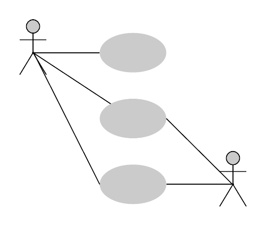
UML Use Case Diagram Examples
What are your diagramming needs, i want to make my own diagram in lucidchart., i want to make diagram from a lucidchart template..
Lucidchart is a diagramming solution for UML with deep integration with third-party apps. Make the diagram itself in Lucidchart, and create your use case scenario document with a program like Google Docs!
3 minute read
Want to make a Diagram of your own? Try Lucidchart. It's quick, easy, and completely free.
What is a use case diagram in UML?
Outline your use case diagram.
Use case scenario documents break down a process by describing the actors, the typical workflow, and the things that could go wrong, called extensions. When managing projects that use UML conventions, there can be a temptation to jump straight into the use case diagram, with stick figures, ovals, and lots of lines. But if you don’t know your goals and who’s involved, take a step back and write your goals down in prose. Alistair Cockburn is a leader in designing use case scenarios; visit his website to get inspired!
This is a brief example the process of withdrawing money from an ATM. The outline goes through each of the steps that are likely to occur in the process, including each of the errors that could likely occur. Outlining the process like this will help you to outline the process, making the act of diagramming your use case scenario easier than ever.

Diagramming is quick and easy with Lucidchart. Start a free trial today to start creating and collaborating.
Use case diagram examples in Lucidchart
Book publishing use case diagram example.
This use case diagram is a visual representation of the prose scenario shown above. Whether you’re an author, an agent, or a bookseller, inserting this diagram into your use case scenario can help your team publish the next big hit. Try our demo template for a book publishing use case diagram here.

Railway reservation use case diagram example
This customizable template can be adapted for any process where a customer is purchasing a service. With attractive color schemes, text that’s easy to read and edit, and a wide-ranging UML shape library, you’re ready to go! Jump right in and try our demo template to get started.
Banking system use case diagram example
Modern banking systems need to have clear objectives. This diagram presents a high-level overview of some of the most fundamental goals a customer has with his or her bank—opening an account, checking a balance, and withdrawing money. If you like this template try it out in Lucidchart for a banking system use case diagram here.
How to make a use case diagram
In Lucidchart, creating a use case diagram from scratch is surprisingly simple.
Create a use case scenario document to organize the process and all possible alternative extensions.
Open a blank Lucidchart document or start with a template and enable the UML shape library.
Select the shape you want and drag out symbols from the toolbox to the canvas
Then model the process flow by drawing lines between shapes while adding text.
Dive deeper into this guide on how to draw a use case diagram in UML for additional insight. It's easy to resize and style any element. You can even import SVG shapes and Visio files for a custom solution. If you'd like to learn more about UML, check out our What is UML tutorial.
Additional Resources
- What is an BPMN and how to create one
- How to Make a Synoptic Table in Excel
- How to Make a Synoptic Chart in PowerPoint
- How to Make a Synoptic Table in Word
- Examples and Templates for Synoptic Tables
- What is and how to create an ERD
- What is an process map and how to create one
- What is a Data Flow Diagram (DFD) and How to Create One
- How to Make a Synoptic Table
- PowerPoint Flowchart Template Guide
- What is an Value Stream Map (VSM) and how to create one
- Workflow diagram tutorial
- What is a Swimlane Diagram and Steps to Create One
- What is an Network Diagram and how to create one
- What is and how to create a decision tree
- P&ID Examples
- How to Draw a Use Case Diagram in UML
Lucidchart is a flexible tool for building use case scenarios in prose or in diagrams. There’s no need to install expensive, slow software when you can edit, perfect, and publish your use case scenarios and diagrams from your browser!
UML Use Case Diagram: Tutorial with EXAMPLE
What is the Use Case Diagram?
Use Case Diagram captures the system’s functionality and requirements by using actors and use cases. Use Cases model the services, tasks, function that a system needs to perform. Use cases represent high-level functionalities and how a user will handle the system. Use-cases are the core concepts of Unified Modelling language modeling.
Why Use-Case diagram?
A Use Case consists of use cases, persons, or various things that are invoking the features called as actors and the elements that are responsible for implementing the use cases. Use case diagrams capture the dynamic behaviour of a live system. It models how an external entity interacts with the system to make it work. Use case diagrams are responsible for visualizing the external things that interact with the part of the system.
Use-case diagram notations
Following are the common notations used in a use case diagram:
Use cases are used to represent high-level functionalities and how the user will handle the system. A use case represents a distinct functionality of a system, a component, a package, or a class. It is denoted by an oval shape with the name of a use case written inside the oval shape. The notation of a use case in UML is given below:

It is used inside use case diagrams. The actor is an entity that interacts with the system. A user is the best example of an actor. An actor is an entity that initiates the use case from outside the scope of a use case. It can be any element that can trigger an interaction with the use case. One actor can be associated with multiple use cases in the system. The actor notation in UML is given below.

How to draw a use-case diagram?
To draw a use case diagram in UML first one need to analyse the entire system carefully. You have to find out every single function that is provided by the system. After all the functionalities of a system are found out, then these functionalities are converted into various use cases which will be used in the use case diagram.
A use case is nothing but a core functionality of any working system. After organizing the use cases, we have to enlist the various actors or things that are going to interact with the system. These actors are responsible for invoking the functionality of a system. Actors can be a person or a thing. It can also be a private entity of a system. These actors must be relevant to the functionality or a system they are interacting with.
After the actors and use cases are enlisted, then you have to explore the relationship of a particular actor with the use case or a system. One must identify the total number of ways an actor could interact with the system. A single actor can interact with multiple use cases at the same time, or it can interact with numerous use cases simultaneously.
Following rules must be followed while drawing use-case for any system:
- The name of an actor or a use case must be meaningful and relevant to the system.
- Interaction of an actor with the use case must be defined clearly and in an understandable way.
- Annotations must be used wherever they are required.
- If a use case or an actor has multiple relationships, then only significant interactions must be displayed.
- State Machine Diagram & Statechart Diagram in UML
- UML Relationships Types: Association, Dependency, Generalization
- UML Association Vs. Aggregation Vs. Composition [EXAMPLE]
Tips for drawing a use-case diagram
- A use case diagram should be as simple as possible.
- A use case diagram should be complete.
- A use case diagram should represent all interactions with the use case.
- If there are too many use cases or actors, then only the essential use cases should be represented.
- A use case diagram should describe at least a single module of a system.
- If the use case diagram is large, then it should be generalized.
An example of a use-case diagram
Following use case diagram represents the working of the student management system:

In the above use case diagram, there are two actors named student and a teacher. There are a total of five use cases that represent the specific functionality of a student management system. Each actor interacts with a particular use case. A student actor can check attendance, timetable as well as test marks on the application or a system. This actor can perform only these interactions with the system even though other use cases are remaining in the system.
It is not necessary that each actor should interact with all the use cases, but it can happen.
The second actor named teacher can interact with all the functionalities or use cases of the system. This actor can also update the attendance of a student and marks of the student. These interactions of both student and a teacher actor together sums up the entire student management application.
When to use a use-case diagram?
A use case is a unique functionality of a system which is accomplished by a user. A purpose of use case diagram is to capture core functionalities of a system and visualize the interactions of various things called as actors with the use case. This is the general use of a use case diagram.
The use case diagrams represent the core parts of a system and the workflow between them. In use case, implementation details are hidden from the external use only the event flow is represented.
With the help of use case diagrams, we can find out pre and post conditions after the interaction with the actor. These conditions can be determined using various test cases.
In general use case diagrams are used for:
- Analyzing the requirements of a system
- High-level visual software designing
- Capturing the functionalities of a system
- Modeling the basic idea behind the system
- Forward and reverse engineering of a system using various test cases.
Use cases are intended to convey desired functionality so the exact scope of a use case may vary according to the system and the purpose of creating UML model.
- Use case diagrams are a way to capture the system’s functionality and requirements in UML diagrams .
- It captures the dynamic behavior of a live system.
- A use case diagram consists of a use case and an actor.
- A use case represents a distinct functionality of a system, a component, a package, or a class.
- An actor is an entity that initiates the use case from outside the scope of a use case.
- A purpose of use case diagram is to capture the core functionalities of a system.
EdrawMax – Easy Diagram App
Make a diagram in 3 steps.
UML Use Case Examples

What is a Use Case Diagram?
When a system software is in the developing phase, then for making it perform efficiently, the developers specify different use cases to check the possible behavior of the software in different cases or situations. This diagram shows us the possible behavior of how the software will perform.
The benefit of using the use case diagram is that we develop the system with the user in mind. It is the best way to meet the requirements of the end-user. The use case diagram illustrates the relationship between the multiple use-cases, actors, and systems. The best practice is that the use case diagram should be small and crispy. The use case diagram specifies how a system will perform, which is why it shows only the functionality of the system.
Use Case Diagram Notation
In this section, we will talk about the four basic types of use case diagram notations. They are as follows.

The use cases tell us about how the system will perform in different cases. These use cases are made by keeping in mind what a user wants from the system. Depending on the user's wants and needs, the use cases are made, and then the system is developed and tested according to these cases.

An actor is simply the end-user. That can be anyone, a human, an organization, a machine, or anything. The actors are placed with different cases on the diagram to illustrate how the user will interact with the system.

The subsystems in the UML are the different fixed systems that behave independently in a system. They are used in UML diagrams to represent different units in the system.
Relationships in the Use Case Diagram

They show the relationship between the model elements. It shows the behavior between model elements.
Source: www.ibm.com
All-in-One Diagram Software
- Superior file compatibility: Import and export drawings to various file formats, such as Visio
- Cross-platform supported (Windows, Mac, Linux, Web)
Use Case Diagram Examples of Common Scenarios
This section will present multiple practical use case diagram examples that will clear out the mind and concept.
1. Use Case Diagram for ATM

The Automatic Teller Machine (ATM) is the banking subsystem that enables the end-users to interact with the multiple functionalities of the bank like transactions, depositing, etc.
In this diagram, we have two actors, the customer, and the technician. The customer needs to check the balance, withdraw cash, deposit funds, and transfer funds. All these functionalities are the use cases. The technician repairs and maintains the ATM so that customers have no complaints. These are the use-cases too.
There is a relationship between the bank and the ATM because the user will only do such acts when the bank authenticates them.
2. Use Case Diagram for Website

In the above diagram, the site user and the webmaster are the actors of the UML diagram. The site user wants to search for documents, browse documents, and view events. These are the use cases or the functionality the user wants to do. The download and preview documents are the use cases too, and they are in relation to each other based on user requirements.
The webmaster upload documents, post new events to the homepage and add a user and these use cases are in relation with the managed folders and add company but still based on what the actor wants.
3. Use Case Diagram for Library Management System

In the diagram, we can see the multiple actors: staff and the student, librarian, and library database. And we have dozens of use cases like authenticating, reserve a book, renewing a book, paying a fine, etc. Some use cases are related to each other, like invalid renewal and renewing a book, registering a new user, getting a library card ID, etc.
The librarian also does multiple tasks. The thing to notice here is that one actor is a machine that is the library database. As mentioned above, the actor can be anyone, either a human and a machine.
4. Use Case Diagram for Online Shopping

In this illustration, we have an online shopping subsystem. It has use cases like view items, make a purchase, checkout, and client register. Then we have multiple actors like the registered user, web customer, and new customer. These actors are related to each other. The use cases are also in a relationship.
The actors PayPal and credit payment service are the organizations interacting with the subsystem with different use-cases.
5. Use Case Diagram for Hospital Management System

Source: www.uml-diagrams.org
It is the use case diagram of the hospital management system. In this diagram, the receptionist is the leading actor. The receptionist interacts with multiple use cases like a scheduled patient appointment, patient admission in the hospital, etc. These cases are related to each other.
6. Use Case Diagram for Car Rental System

It is an illustration of the car rental system use-case UML. Here, the insurance company is the actor that is the organization interacting with bill payment use-case and the customer is also an actor. Through the customer, the insurance company is also interacting with other use-cases of the car rental system. The employee and the manager are also the actors in this system.
7. Use Case Diagram for Student Registration System

Source: www.researchgate.net
It is the student registration system use-case UML diagram. Students, professors, and administrators are the actors. The system also has dozens of use-cases.
8. Use Case Diagram for Airline Reservation System

This system is the subsystem of the airline reservation system. The actors are passengers, admins, and the banks that are the organizations. The passenger is concerned with multiple use cases like login, check for availability, book ticket, etc. The book ticket use case is in relation to the choose seat use case. The admin cancels tickets, updates flight schedules. The bank sees the payment use cases.
Click the video below to learn more about how to create UML Modeling and EdrawMax .
Use EdrawMax for Use Case Diagram Creation
Describing your system with a use case diagram before developing is essential in itself. It helps you to understand what the user needs. It helps you in making system functions more feasible. The best thing is that the use cases are visible. It helps you in testing and improving the software quickly. The use case diagram helps you to make your product user-friendly.
You can use EdrawMax to make a use case diagram. EdrawMax is the best diagram-making software that helps you to make any diagram efficiently. The software contains all the packages and libraries that will suffice you in your diagram-making.
EdrawMax allows you to import your templates or use pre-generated examples to make your production faster. You are allowed to export your project to any site. The software is free to use for the preliminary work, but you have to go for the pricing options for premium features.

- Announcements
- Brainstorming
- Development
- HR Planning
- Infographics
- IT & Operations
- Marketing & Sales
- Meeting & Visual Collaboration
- Product Management
- Production & Manufacturing
- Project Management
- Remote Working
- Research & Analysis
- Software Teams
- Strategy & Planning
- Template Roundup
- Uncategorized

Use Case Diagram Relationships Explained with Examples
Updated on: 13 December 2022
When it comes to drawing use case diagrams one area many struggles with is showing various relationships in use case diagrams. In fact many tend to confuse <<extend>>, <<include>> and generalization. This article will look into various use case diagram relationships in detail and explain them using examples. To get a deeper understanding of use cases, check out our use case diagram tutorial . If you want to draw them while learning you can use our tool to create use case diagrams .
There can be 5 relationship types in a use case diagram.
- Association between actor and use case
- Generalization of an actor
- Extend between two use cases
- Include between two use cases
- Generalization of a use case
Let’s take a look at these relationships in detail.
Association Between Actor and Use Case
This one is straightforward and present in every use case diagram. Few things to note.
- An actor must be associated with at least one use case.
- An actor can be associated with multiple use cases.
- Multiple actors can be associated with a single use case.

Different ways association relationship appears in use case diagrams
Check out the use case diagram guidelines for other things to consider when adding an actor.
Generalization of an Actor
Generalization of an actor means that one actor can inherit the role of the other actor. The descendant inherits all the use cases of the ancestor. The descendant has one or more use cases that are specific to that role. Let’s expand the previous use case diagram to show the generalization of an actor.

A generalized actor in an use case diagram
Extend Relationship Between Two Use Cases
Many people confuse the extend relationship in use cases. As the name implies it extends the base use case and adds more functionality to the system. Here are a few things to consider when using the << extend >> relationship.
- The extending use case is dependent on the extended (base) use case . In the below diagram the “Calculate Bonus” use case doesn’t make much sense without the “Deposit Funds” use case.
- The extending use case is usually optional and can be triggered conditionally. In the diagram, you can see that the extending use case is triggered only for deposits over 10,000 or when the age is over 55.
- The extended (base) use case must be meaningful on its own . This means it should be independent and must not rely on the behavior of the extending use case.
Lets expand our current example to show the <<extend>> relationship.

Extend relationship in use case diagrams
Although extending use case is optional most of the time it is not a must. An extending use case can have non-optional behavior as well. This mostly happens when your modeling complex behaviors.
For example, in an accounting system, one use case might be “Add Account Ledger Entry”. This might have extending use cases “Add Tax Ledger Entry” and “Add Payment Ledger Entry”. These are not optional but depend on the account ledger entry. Also, they have their own specific behavior to be modeled as a separate use case.
Include Relationship Between Two Use Cases
Include relationship show that the behavior of the included use case is part of the including (base) use case. The main reason for this is to reuse common actions across multiple use cases. In some situations, this is done to simplify complex behaviors. Few things to consider when using the <<include>> relationship.
- The base use case is incomplete without the included use case.
- The included use case is mandatory and not optional.
Lest expand our banking system use case diagram to show include relationships as well.

Includes is usually used to model common behavior
For some further reading regarding the difference between extend and include relationships in use case diagrams check this StackOverflow link .
Generalization of a Use Case
This is similar to the generalization of an actor. The behavior of the ancestor is inherited by the descendant. This is used when there is common behavior between two use cases and also specialized behavior specific to each use case.
For example, in the previous banking example, there might be a use case called “Pay Bills”. This can be generalized to “Pay by Credit Card”, “Pay by Bank Balance” etc.
I hope you found this article about use case relationships helpful and useful. You can use our diagramming tool to easily create use case diagrams online . As always if you have any questions don’t hesitate to ask them in the comments section.
Join over thousands of organizations that use Creately to brainstorm, plan, analyze, and execute their projects successfully.

More Related Articles

Many thanks for this great tutorial. It is really very clear with good examples and explanation methodology and most probably one of the best UML Tutorial on the web. Hope to come across such kind of good tutorials again…
Great tutorial! It’s probably the best one I’ve read
Does an included use case have to be used everytime the base case is used?
yes it does. the included use case is always be used everytime the base use case used. it’s like when someone’s sneezing he always close his eyes. sneezing is the base use case and closing eyes is the included use case.
is it possible to make extensions within a use case itself.
Yes, “The same extending UseCase can extend more than one UseCase. Furthermore, an extending UseCase may itself be extended.” – UML 2.5.1 Specification.
Found it better than other tutorials…. explaining everything as part of the development process. Thanks, hope to see other tutorials on OOAD and other topics.
This tutorial helped me to understand the difference between include and extend. Keep it up bro. Good luck!
Question: There are two sub usecases in a genaralized one. If I want a include to be attached to which one do I attach it. The main Usecase or the sub usecase
Awesome article … well and clearly explained all the concepts in use case diagrams
why use <> in use case?
In Visual Modeling we model according to some standard. Every shape or sign has a meaning.To draw relationship between Use cases we use to express the type of relationship by mentioning relationship type within . It’s a standard.
Fantastic. This is the most succinct and precise explanation of use case and their relationships that I have ever come across. Thanks
I agree – the best tutorial explaining the relationships that it can truly be understood! Thanks!!
What is the difference between “Extend” and “Generalization”?
I was preparing for my CBAP exam and this post helped me understand the difference between Extend and Include. Thanks.
what is diference between use case and use case modeling
A use case is a functionality performed by an actor(primary,secondary or offstage) Use case modeling is a process of drawing use cases in some modeling languages e.g StarUml
Nice tutorial, very helpful. Thanks a lot 🙂
Awesome Tutorial. now i understood use-case-relationship……..
Super Tutorial….. very very helpful for me to learn about Use Case Diagram……Thank u very much and I have a grate proud about u as a Sri Lankan. Keep up.
not generalized but specialised
Good tutorial! Really helpful for me
Leave a comment Cancel reply
Please enter an answer in digits: thirteen + seventeen =
Download our all-new eBook for tips on 50 powerful Business Diagrams for Strategic Planning.
- About Techcanvass
- Techcanvass Reviews
Data Analytics Fundamentals Course
Project Management Fundamentals Course
Agile Scrum Foundation Course
DevOps Training for Managers
- ALL COURSES
- Business Analysis Courses
BA Training with Domain
Domain training courses.
- Data Analytics Courses
- Self-Learning Courses
- Question Banks
Mini Courses
Core business analysis.
- ECBA Certification Training
- CCBA Certification Training
- CBAP Certification Training
- CBAP Recertification Course
Specialized BA Courses
- Agile Analysis Certification Course
- CPOA Certification Course
- IIBA CBDA Certification Course
Self-Learning/On-Demand Courses
- CBAP On-Demand Course
- CCBA On-Demand Course
- ECBA Self-Learning Course
- PSM Self-Learning Course
- CBDA Self-Learning Course
- AAC Self-Learning Course
- CPOA Self-Learning Course
Domain Training
Banking Domain Training
Insurance Domain Training
Payment Domain Training
Telecom Domain Training
Supply Chain Domain Training
- US Healthcare Domain Training
Live Online Training
Investment Banking Domain Training
Trade Finance Domain Training
Data Analytics Certification Training
IIBA CBDA Certification Course
Data Analytics Basics Course (Free)
Power BI Certification Training
Tableau Training
IIBA Question Bank
- ECBA Question Bank
- CCBA Question Bank
- AAC Question Bank
- CBAP Question Bank
- CBDA Question Bank
- CPOA Question Bank
- MS Visio/ UML Certification
- SQL Certfication for Business Analyst
- UML Training/UML Modelling Course
- Jira Training
- MS Project Training
- Confluence Training
- Business Analyst Interview Preparation
- Question Bank
Back to Menu
ECBA Certification Training
CCBA Certification Training
CBAP Certification Training
CBAP Recertification Course
Agile Analysis Certification Course
CPOA Certification Course
BA Training with Banking Domain
BA Training with Healthcare Domain
BA Training with Investment Banking Domain
CBAP On-Demand Course
CCBA On-Demand Course
ECBA Self-Learning Course
PSM Self-Learning Course
CBDA Self-Learning Course
AAC Self-Learning Course
CPOA Self-Learning Course
US HealthCare Domsin Training
Live Onlive Training
Data analytics training.
ECBA Question Bank
CCBA Question Bank
AAC Question Bank
CBAP Question Bank
CBDA Question Bank
CPOA Question Bank
MS Visio / UML Certification Course
SQL Certification For Business Analyst
UML Training/UML Modelling Course
Jira Training
MS Project Training
Confluence Training
Business Analyst Interview Preparation
Free Courses
Use case case study – uml modelling.
In this Use Case case study, I am going to present a case study of the airport check-in system. The case study includes the identification of actors, use cases and scenarios including activity diagrams. I have used a generic case study approach and can be used in any software project. This case study is useful for every business analysis study.
The sequence diagram for the same case study will be covered in some other post as that would have made this post too long.
Table of Contents
- 1. Case study description
- 2. Use Case Modelling steps
- 3. Conclusion
Case study description
This proposed software system is to be designed to allow passengers to check in and get the boarding pass for flying. The baggage can also be checked in, which is optional. The check-in can happen by the counter clerk or by the passenger using the kiosk.
The system should allow individuals as well as groups of passengers to check in through the system. The boarding pass can be issued through this system. Passengers below 4 yrs need not have tickets. The airport also allows provisioning for the special needs of passengers like wheelchairs etc.
The system should also be able to capture the fact that the baggage for a passenger is screened by security.
Use Case Modelling steps
Use case modelling can be done in multiple ways. One of the standard processes is known as Rational Unified Process (RUP), this process is put forward by Rational Inc., now under Oracle.
In this article, I am going to suggest a process, which I used in my projects in various software companies. As per this process, the steps involved are as follows, these steps are for complete system analysis and design using UML models. However, in this article, we will look at only use case modelling steps:
- Understand the business domain, context and needs
- Conduct Stakeholder Analysis
- Interact with stakeholders to understand stakeholders needs
- Find structural elements/functions – functional decomposition
- Use cases identification & create use case model
- Identify scenarios
- Create activity diagrams
- Create sequence diagram, if needed
- Identify classes and build logical data model
- System design
Step1: Identify actors
The first step is to identify the actors from the given requirements. Actors are external entities, who interact with the system, to be developed. All the nouns used in the requirements could be actors. In our case, the possible candidates for being actors could be:
- Passengers with age <= 4 yrs
- Passengers with special needs
- Group of passengers
- Check-in clerk
Identification of actors is an iterative activity, where we can refine the selection of actors. If you look at the actors' list, you can see that there are multiple types of passengers. This means that an actor namely Passengers has related actors. The actors can be shown as shown below:
Step 2: Identify use cases
Once we have identified actors, we can focus on the interactions of the actors with the system. In our case of the airline system, we can identify the following use cases:
This functional mapping is an excellent way of functional decomposition as well as identification of use cases. Based on the above functional map, we can go ahead to create the use case model. A detailed use case model is shown below:
The use cases are kept within the system boundaries with proper “Include” and “Exclude” relationships.
If you want to brush up on your basics of Use cases and UML, you can read this blog: What Is Use Case Basics & Diagrams?
Step 3: Identify scenarios
Once we identify the use cases and build the use case model, the next step is to identify scenarios. The scenarios add details to the use case model. Scenarios also help in identifying business processes and creating activity diagrams.
Typically speaking, every use case may result in one or more scenarios. However, it’s not mandatory to make activity diagrams for each of the use cases. Every model diagram is created only if it helps in understanding the system better.
Scenarios can be of two types:
- Success scenario, when everything works fine
- Error/Alternate scenarios
Let’s see the scenarios for the check-in process:-
Success Scenario: Check-in process getting completed without any issues
- Individual puts the baggage for check-in and stickers
- Shows the ticket to the booking clerk at the booking counte
- The booking clerk enters the PNR number and verifies the data
- The booking clerk asks for an ID card and verifies
- The passenger puts the baggage and the weight is checked by the booking clerk
- The baggage stickers are printed and attached to the baggage
- The boarding pass is issued to the passenger
Alternate Scenario: Check-in process for Individuals having special needs
- Identify the passengers with “Special needs”
- An alert is sent to the customer service desk
There are other alternate scenarios in this case, I am not writing the steps for them. You can try that as exercise.
i. Alternate Scenario: Baggage weight > Allowed limit ii. Alternate Scenario: Valid ID card not available iii. Alternate Scenario: Passenger checks in using Kiosk Having identified the scenarios, the next step is to create the activity diagram.
Step 4: Creating activity diagrams
The activity diagrams can be created on the basis of identified steps and scenarios. You can use a tool to create the activity diagrams or use Microsoft Word or Powerpoint as well.
For our case study, the activity diagram is:
This is a type of case study, which are part of all of our business analysis courses, where we help participants to do it themselves so that they can get hands-on experience.
The use of use cases is an essential technique for business analysts to understand the requirements of stakeholders and build effective software solutions. Through the case study discussed in this article, we have seen how use cases can be applied in real-life scenarios to identify and analyze business requirements, document functional specifications, and develop robust software solutions that meet customer needs.
By following a structured approach to use case development, business analysts can ensure that the software solutions they develop are aligned with business objectives, meet user expectations, and deliver measurable business benefits.
Have you considered getting certified in business analysis but are unsure of which certification to pursue?
Consider getting certified as a Certified Business Analysis Professional (CBAP) by Techcanvass. The CBAP certification is a globally recognized certification that validates your expertise in business analysis and positions you as a leader in the field.
With Techcanvass's CBAP certification training program , you will gain a competitive edge in the job market and open up opportunities for career growth and development. In our training program, we cover tools like UMLet , yUML , and WebSequenceDiagrams . You will get access to all the study material, live instructor-led training, doubt-clearing sessions, and much more.
Comments
Leave a comment
Your email address will not be published. Required fields are marked
POST COMMENT
Comment inserted Successsfully
Please login to Comment
Lorem Ipsum is simply dummy text of the printing and typesetting industry. Lorem Ipsum has been the industry's standard dummy text
Related Blogs

| JOIN WEBINAR | |
Copyright © Techcanvass | All Rights Reserved
- Interview Q
UML Tutorial

| A use case diagram is used to represent the dynamic behavior of a system. It encapsulates the system's functionality by incorporating use cases, actors, and their relationships. It models the tasks, services, and functions required by a system/subsystem of an application. It depicts the high-level functionality of a system and also tells how the user handles a system. The main purpose of a use case diagram is to portray the dynamic aspect of a system. It accumulates the system's requirement, which includes both internal as well as external influences. It invokes persons, use cases, and several things that invoke the actors and elements accountable for the implementation of use case diagrams. It represents how an entity from the external environment can interact with a part of the system. Following are the purposes of a use case diagram given below: It is essential to analyze the whole system before starting with drawing a use case diagram, and then the system's functionalities are found. And once every single functionality is identified, they are then transformed into the use cases to be used in the use case diagram. After that, we will enlist the actors that will interact with the system. The actors are the person or a thing that invokes the functionality of a system. It may be a system or a private entity, such that it requires an entity to be pertinent to the functionalities of the system to which it is going to interact. Once both the actors and use cases are enlisted, the relation between the actor and use case/ system is inspected. It identifies the no of times an actor communicates with the system. Basically, an actor can interact multiple times with a use case or system at a particular instance of time. Following are some rules that must be followed while drawing a use case diagram: A use case diagram depicting the Online Shopping website is given below. Here the Web Customer actor makes use of any online shopping website to purchase online. The top-level uses are as follows; View Items, Make Purchase, Checkout, Client Register. The use case is utilized by the customer who searches and view products. The use case allows the customer to register itself with the website for availing gift vouchers, coupons, or getting a private sale invitation. It is to be noted that the is an included use case, which is part of and it is not available by itself. is further extended by several use cases such as; Search Items, Browse Items, View Recommended Items, Add to Shopping Cart, Add to Wish list. All of these extended use cases provide some functions to customers, which allows them to search for an item. The View Items is further extended by several use cases such as; Search Items, Browse Items, View Recommended Items, Add to Shopping Cart, Add to Wish list. All of these extended use cases provide some functions to customers, which allows them to search for an item.Both and include the Customer Authentication use case, as they necessitate authenticated customers, and simultaneously item can be added to the shopping cart without any user authentication. use case also includes the following use cases, as shown below. It requires an authenticated Web Customer, which can be done by login page, user authentication cookie ("Remember me"), or Single Sign-On (SSO). SSO needs an external identity provider's participation, while Web site authentication service is utilized in all these use cases.The Checkout use case involves Payment use case that can be done either by the credit card and external credit payment services or with PayPal. Following are some important tips that are to be kept in mind while drawing a use case diagram: |

- Send your Feedback to [email protected]
Help Others, Please Share

Learn Latest Tutorials

Transact-SQL

Reinforcement Learning

R Programming

React Native

Python Design Patterns

Python Pillow

Python Turtle

Preparation

Verbal Ability
Interview Questions

Company Questions
Trending Technologies

Artificial Intelligence

Cloud Computing

Data Science

Machine Learning

B.Tech / MCA

Data Structures

Operating System

Computer Network

Compiler Design

Computer Organization

Discrete Mathematics

Ethical Hacking

Computer Graphics

Software Engineering

Web Technology

Cyber Security

C Programming

Control System

Data Mining

Data Warehouse

- UML Tutorial
- UML - Overview
- UML - Building Blocks
- UML - Architecture
- UML - Modeling Types
- UML - Basic Notations
- UML - Standard Diagrams
- UML - Class Diagram
- UML - Object Diagram
- UML - Component Diagram
- UML - Deployment Diagram
- UML - Use Case Diagram
- UML - Interaction Diagram
- UML - Statechart Diagram
- UML - Activity Diagram
- UML - Summary
- UML 2.0 Overview
- UML 2.0 - Overview
- UML Useful Resources
- UML - Useful Resources
- UML - Knowledge Test
- UML - Tools & Utilities
- UML - Discussion
- Selected Reading
- UPSC IAS Exams Notes
- Developer's Best Practices
- Questions and Answers
- Effective Resume Writing
- HR Interview Questions
- Computer Glossary
UML - Use Case Diagrams
To model a system, the most important aspect is to capture the dynamic behavior. Dynamic behavior means the behavior of the system when it is running/operating.
Only static behavior is not sufficient to model a system rather dynamic behavior is more important than static behavior. In UML, there are five diagrams available to model the dynamic nature and use case diagram is one of them. Now as we have to discuss that the use case diagram is dynamic in nature, there should be some internal or external factors for making the interaction.
These internal and external agents are known as actors. Use case diagrams consists of actors, use cases and their relationships. The diagram is used to model the system/subsystem of an application. A single use case diagram captures a particular functionality of a system.
Hence to model the entire system, a number of use case diagrams are used.
Purpose of Use Case Diagrams
The purpose of use case diagram is to capture the dynamic aspect of a system. However, this definition is too generic to describe the purpose, as other four diagrams (activity, sequence, collaboration, and Statechart) also have the same purpose. We will look into some specific purpose, which will distinguish it from other four diagrams.
Use case diagrams are used to gather the requirements of a system including internal and external influences. These requirements are mostly design requirements. Hence, when a system is analyzed to gather its functionalities, use cases are prepared and actors are identified.
When the initial task is complete, use case diagrams are modelled to present the outside view.
In brief, the purposes of use case diagrams can be said to be as follows −
Used to gather the requirements of a system.
Used to get an outside view of a system.
Identify the external and internal factors influencing the system.
Show the interaction among the requirements are actors.
How to Draw a Use Case Diagram?
Use case diagrams are considered for high level requirement analysis of a system. When the requirements of a system are analyzed, the functionalities are captured in use cases.
We can say that use cases are nothing but the system functionalities written in an organized manner. The second thing which is relevant to use cases are the actors. Actors can be defined as something that interacts with the system.
Actors can be a human user, some internal applications, or may be some external applications. When we are planning to draw a use case diagram, we should have the following items identified.
Functionalities to be represented as use case
Relationships among the use cases and actors.
Use case diagrams are drawn to capture the functional requirements of a system. After identifying the above items, we have to use the following guidelines to draw an efficient use case diagram
The name of a use case is very important. The name should be chosen in such a way so that it can identify the functionalities performed.
Give a suitable name for actors.
Show relationships and dependencies clearly in the diagram.
Do not try to include all types of relationships, as the main purpose of the diagram is to identify the requirements.
Use notes whenever required to clarify some important points.
Following is a sample use case diagram representing the order management system. Hence, if we look into the diagram then we will find three use cases (Order, SpecialOrder, and NormalOrder) and one actor which is the customer.
The SpecialOrder and NormalOrder use cases are extended from Order use case. Hence, they have extended relationship. Another important point is to identify the system boundary, which is shown in the picture. The actor Customer lies outside the system as it is an external user of the system.

Where to Use a Use Case Diagram?
As we have already discussed there are five diagrams in UML to model the dynamic view of a system. Now each and every model has some specific purpose to use. Actually these specific purposes are different angles of a running system.
To understand the dynamics of a system, we need to use different types of diagrams. Use case diagram is one of them and its specific purpose is to gather system requirements and actors.
Use case diagrams specify the events of a system and their flows. But use case diagram never describes how they are implemented. Use case diagram can be imagined as a black box where only the input, output, and the function of the black box is known.
These diagrams are used at a very high level of design. This high level design is refined again and again to get a complete and practical picture of the system. A well-structured use case also describes the pre-condition, post condition, and exceptions. These extra elements are used to make test cases when performing the testing.
Although use case is not a good candidate for forward and reverse engineering, still they are used in a slightly different way to make forward and reverse engineering. The same is true for reverse engineering. Use case diagram is used differently to make it suitable for reverse engineering.
In forward engineering, use case diagrams are used to make test cases and in reverse engineering use cases are used to prepare the requirement details from the existing application.
Use case diagrams can be used for −
Requirement analysis and high level design.
Model the context of a system.
Reverse engineering.
Forward engineering.
UML Use Case Diagram Examples
Here we provide some examples of UML use case diagrams .
Examples of business use case diagrams
Purpose : An example of a business use case diagram for airport check-in and security screening.
Summary : Business use cases are Individual Check-In, Group Check-In (for groups of tourists), Security Screening, etc. - representing business functions or processes taking place in an airport and serving needs of passengers.

Purpose : Two alternative examples of business use case diagram for a Restaurant - external and internal business views of a restaurant.
Summary : Several business actors having some needs and goals as related to the restaurant and business use cases expressing expectations of the actors from the business.

Examples of system use case diagrams
Purpose : Show that ticket vending machine allows commuters to buy tickets.
Summary : The ultimate goal of a Commuter in relation to our ticket vending machine is to buy a ticket. We have a single Purchase Ticket use case, as this vending machine is not providing any other services. Ticket vending machine is a subject of the example use case diagram. Commuter and Bank are our actors , both participating in the Purchase Ticket use case .

Purpose : Describe use cases that an automated teller machine (ATM) or the automatic banking machine (ABM) provides to the bank customers.
Summary : Customer uses a bank ATM to check balances of his/her bank accounts, deposit funds, withdraw cash and/or transfer funds (use cases). ATM Technician provides maintenance and repairs to the ATM.

Purpose : An example of use cases for a Point of Sale (POS) Terminal or Checkout in a supermarket.
Summary : Checkout use case involves Customer, Clerk and Credit Payment Service actors and includes scanning items, calculating total and taxes, and payment use cases. This is an example of a large and complex use case split into several smaller use cases.
 terminal UML use case diagram examples.")
Purpose : List top level use cases for e-Library online public access catalog.
Summary : Patrons of a library can search library catalog online to locate various resources - books, periodicals, audio and visual materials, or other items under control of the library. Patrons may reserve or renew item, provide feedback, and manage their account.
 UML use case diagram example.")
Purpose : Provide top level use cases for a web customer making purchases online.
Summary : Web customer actor uses some web site to make purchases online. Top level use cases are View Items , Make Purchase and Client Register .

Purpose : Define major use cases for a credit card processing system ( credit card payment gateway ).
Summary : The merchant submits a credit card transaction request to the credit card payment gateway on behalf of a customer. Bank which issued customer's credit card is actor which could approve or reject the transaction. If transaction is approved, funds will be transferred to merchant's bank account.

Purpose : Website management or administration UML use case diagrams example.
Summary : Website Administrator actor could manage user groups, users, user sessions, and logs. Help Desk staff uses a subset of functions available to the Website Administrator.

Purpose: Describe major services (functionality) provided by a hospital's reception.
Summary : This UML use case diagram example shows actor and use cases for a hospital's reception. Hospital Reception subsystem or module supports some of the many job duties of a hospital receptionist. Receptionist schedules patient's appointment and admission to the hospital, collects information from the patient by phone and/or upon patient's arrival to the hospital.
For the patient that will stay in the hospital ("inpatient") she or he should have a bed allotted in a ward. Receptionists might also receive patient's payments, record them in a database and provide receipts, file insurance claims and medical reports.

Purpose: Radiology diagnostic reporting UML use case diagram example for Simple Image and Numeric Report (SINR) IHE Radiology Integration Profile.
Summary : In the initial stage of diagnostic reporting, a reading physician records a diagnosis by generating a draft DICOM Structured Report (SR) object. Report Creator actor transmits that DICOM SR object to the Report Manager. External Report Repository Access actor is a gateway to obtain other enterprise department reports, such as Laboratory and Pathology, from within the Imaging department.

Purpose: Use case diagram example shows some simplified view of software licensing use cases supported by Sentinel EMS Application.
Summary : Sentinel License Development Kit (Sentinel LDK) is a Software Digital Rights Management (DRM) solution by SafeNet Inc. that delivers strong copy protection, protection for Intellectual Property (IP), and secure and flexible licensing. The Sentinel EMS application handles three major workflows - license planning, order processing and production, and activation of trial software.

- Start free trial
Start selling with Shopify today
Start your free trial with Shopify today—then use these resources to guide you through every step of the process.

How to Write a Use Case for Products (+ Template)
A use case allows you to imagine how a potential customer might use your product—in the ways you intend and in ways that surprise you.

When launching a new product, your vision for its use might differ from how customers actually use it. George Nissen, the gymnast who invented the modern trampoline, probably didn’t expect his exercise equipment would become a popular children’s toy. In other words, he probably didn’t foresee this use case —a product development framework that helps identify target audiences and hone in on your product’s value.
What is a use case?
A use case is a detailed description of how something is used to achieve a specific goal. For example, the use case for your refrigerator is storing food at low temperatures to prevent spoilage.
Formal use cases are commonly used in software development to map out how a hypothetical user will interact with a new feature. Other industries create use cases to identify key audiences and develop products that satisfy their needs.
How use cases work in software development
In the tech industry, a use case is a detailed document outlining the steps a user takes to achieve a goal using a not-yet-developed product, typically a new software feature.
Different combinations of users, goals, and actions yield different scenarios, and the use case for a single product can include multiple scenarios. The goal of a tech use case is to ensure the software meets user goals and to anticipate potential issues.
For example, in a use case for a mobile banking app, one scenario might involve a user entering incorrect login credentials multiple times, locking them out of their account. By identifying this issue during product research and development , the developers could implement a feature that lets users reset their passwords securely before launch.
How use cases work in other industries
Use cases in industries that make physical products differ from those used in the world of software development. A use case for a physical product focuses less on pinpointing errors and more on understanding and connecting with the target audience.
Developers and marketers of physical products create use cases to identify problems their product will solve for different users. A use case for a new fridge might focus on an ergonomic handle that’s more comfortable for people with arthritis. This would involve asking people with arthritis to test the handle to ensure it meets their needs. Marketing materials could then use language and imagery appealing to this audience.
📖Read more: How To Find a Product to Sell: 16 Proven Methods
Benefits of use cases
Hone in on the product’s value, prioritize key features, gain marketing insights.
A good use case can help you do the following:
Because a use case outlines exactly how your product helps your target audience achieve their goals, it can assist in illustrating your product’s value. Although you don’t share your use case with customers, it informs your unique value proposition and marketing materials.
Exploring different use cases for your product can reveal new, unexpected values and audiences. For example, a desktop mini fridge initially intended for beverages might also appeal to those needing refrigeration for skin care products. In tech, these alternative scenarios describe situations where users “misuse” software—or use it in unexpected ways. By anticipating alternative scenarios for your product, you can provide product attributes that better serve your users.
Understanding how your audience uses your product helps you identify and prioritize essential features or benefits to meet customer needs. This can also help with project planning and budgeting by focusing resources on the most critical features.
The key benefits you identify also form the basis for test cases, which validate the efficacy of your product’s features.
Product marketing relies on use cases to convey a product’s value to various audiences. Tailoring the language in marketing materials to the target audience and their specific use of the product ensures the message resonates.
Aligning your messaging with how your audience views their challenge or problem can make it easier for them to see your product as a solution.
Put your customer data to work with Shopify’s customer segmentation
Shopify’s built-in segmentation tools help you discover insights about your customers, build segments as targeted as your marketing plans with filters based on your customers’ demographic and behavioral data, and drive sales with timely and personalized emails.
How to write a use case for a product
- Select a user
- Describe the user’s goal
- Show how the product helps achieve this goal
- Identify key takeaways
In retail, a use case typically describes how a hypothetical customer interacts with and benefits from your product. You may need several use cases to cover various customer interactions. Our use case template can help you write your first one quickly and can provide a helpful framework for each additional use case.
Here’s how to write your first use case:
1. Select a user
Write a brief description of a hypothetical user from your target audience by asking, “Who is this product for?” Then create a use case for each user you identify.
For example, if your product is a collapsible bike helmet, the user might be an urban professional who rides their bike to a coworking space.
2. Describe the user’s goal
Once you’ve chosen a user, describe their goal or pain point related to your product. Focus on the user’s perspective, incorporating insights from customer feedback , surveys , or social listening . Capture how the user actually perceives their goal or pain point, not how you hope they see their pain point.
For the commuter cyclist, the pain point might be a typical helmet’s clunkiness. They want to stay safe, but their helmet doesn’t fit in their work bag, and there’s nowhere to store it at the coworking space. It’s also inconvenient when meeting friends for dinner after work.
3. Show how the product helps achieve this goal
Explain how the hypothetical user will use your product to solve their problem or achieve their goal. For a physical product, describe when and where they will use it and highlight the most important features or benefits.
There’s only one way to wear a bike helmet—on your head—but different users may be drawn to different features and use it in different settings. For instance, the commuter cyclist wears the collapsible helmet on their commute to the coworking space, then stashes it in their bag while working. They put it back on to meet friends for dinner, then stow it away once at the restaurant, repeating the process for the ride home.
4. Identify key takeaways
A use case isn’t something you write once and never look at again. Use it to help your marketing clearly demonstrate how your product can solve users’ challenges.
For instance, key takeaways from the commuter cyclist use case might include the need for a helmet small enough to fit in a messenger bag, work tote, or backpack. Since users frequently collapse and open the helmet, going from storage mode to biking mode and back again needs to be quick and easy. You can demonstrate this to potential customers in video ads on social media.
📖Read more: Types of Advertising: 14 Ways to Market a Product
Repeat this process for each target audience. You can then compile your product’s use cases into a single document to reference for promotional campaigns.
Product use case example
Most products have a variety of use cases. Consider the Slick Salve lip balm from skin care company Topicals . According to Roxana Ontiveros, product marketing lead at Tropicals, the balm was developed with multiple use cases in mind.
“It’s not only for a person who has existing dryness, but it’s also for people who are on Accutane,” she says. “And then it’s also a good use case for someone who maybe wants a cosmetic benefit. So they want something that’s kind of slick, kind of glossy.”
Even the name Slick Salve captures these different use cases: “Slick” describes the cosmetic appeal of glossy lips, while “salve” conveys its healing properties. For Roxana, use cases are an essential part of her goal of capturing as many audiences as possible while still being specific with the product storytelling and messaging.
What is a use case FAQ
What is the difference between a scenario and a use case.
In software development, a scenario (or use case instance) describes a single instance of a hypothetical user interacting with the product to achieve their goal. A use case diagram or document consists of various scenarios. In physical product development, the term use case is commonly employed instead of scenario.
What is the goal of a use case?
The goal of writing a use case is to outline how future users will use your product to meet their goals or needs, or solve their problems. A use case helps you identify target audiences and their needs for product development and marketing.
What is the difference between a use case and a case study?
A case study is a promotional document that tells the story of a real-life customer to prospective customers. A use case is an internal document that describes a hypothetical user and their goals.
Keep up with the latest from Shopify
Get free ecommerce tips, inspiration, and resources delivered directly to your inbox.
By entering your email, you agree to receive marketing emails from Shopify.
popular posts

The point of sale for every sale.

Subscribe to our blog and get free ecommerce tips, inspiration, and resources delivered directly to your inbox.
Unsubscribe anytime. By entering your email, you agree to receive marketing emails from Shopify.
Latest from Shopify
23 Aug 2024
22 Aug 2024
Learn on the go. Try Shopify for free, and explore all the tools you need to start, run, and grow your business.
Try Shopify for free, no credit card required.
Home » UML » ATM System UML Visual Modeling: A Case Study
ATM System UML Visual Modeling: A Case Study
- Posted on August 22, 2024
- / Under UML
- / With 0 Comments
Introduction
Automated Teller Machines (ATMs) have become an integral part of modern banking and financial services. As the demand for convenient and accessible banking solutions continues to grow, the need for robust and efficient ATM systems has become more critical than ever. In this case study, we will explore the visual modeling of an ATM system using the Unified Modeling Language (UML) and the Visual Paradigm for UML tool .
Use Case Diagram
The first step in modeling the ATM system is to identify the key actors and their interactions with the system. The use case diagram provides a high-level overview of the system’s functionalities and the relationships between the actors and the use cases.

The use case diagram illustrates the main functionalities of the ATM system, including withdrawing cash, depositing cash, checking account balance, and transferring funds. It also shows the involvement of bank employees in maintaining the ATM and replenishing the cash supply.
Class Diagram
The class diagram provides a detailed representation of the system’s structure, including the classes, their attributes, and the relationships between them.
The class diagram shows the key components of the ATM system, including the ATMSystem, Card, Account, Customer, and Transaction classes. The relationships between these classes, such as the ATMSystem using a Card and communicating with a BankServer, are also depicted.
Sequence Diagram
The sequence diagram illustrates the dynamic interactions between the actors and the ATM system during a typical transaction.
The sequence diagram shows the step-by-step interactions between the customer, the ATM system, the bank server, the card, and the account during a withdrawal transaction. It demonstrates how the system authenticates the user, retrieves the account balance, processes the withdrawal, and records the transaction with the bank server.
In this case study, we have explored the visual modeling of an ATM system using UML and the PlantUML tool. The use case diagram, class diagram, and sequence diagram provide a comprehensive understanding of the system’s structure, functionality, and dynamic interactions. This type of visual modeling can be invaluable in the design, development, and maintenance of complex systems like ATMs, helping to ensure that the system meets the needs of its users and stakeholders.
Recommendation: Visual Paradigm for UML Modeling
Why Visual Paradigm?
- Visual Paradigm offers a user-friendly, drag-and-drop interface with a clean and intuitive design.
- It provides interactive, real-time visualizations that help users understand and edit models more easily.
- Diagramming: Supports a wide range of UML diagrams, including use case, class, sequence, activity, state machine, and more.
- Code Generation: Allows users to generate code from their UML models, supporting multiple programming languages.
- Reverse Engineering: Can reverse engineer source code into UML models, supporting various programming languages.
- Model Simulation: Enables users to simulate and validate models before implementation.
- Model Transformation: Facilitates automatic model transformation between different diagram types or notations.
- Visual Paradigm supports all 14 standard UML diagram types, plus extensions like SysML, BPMN, and APM.
- It also supports custom diagram types and notations.
- Visual Paradigm integrates with various development environments, including Eclipse, IntelliJ, and Visual Studio.
- It also supports integration with popular version control systems like Git and SVN.
- Offers real-time collaboration with features like shared models, live chat, and version control integration.
- Supports role-based access control, making it suitable for enterprise-level teams.
- Visual Paradigm provides extensive documentation, video tutorials, and a dedicated community forum for support.
- It also offers webinars, training courses, and a free version to help users get started.
- Visual Paradigm offers flexible pricing plans, including a free version for small teams and affordable options for larger enterprises.
- It provides perpetual licenses, annual subscriptions, and volume discounts.
Visual Paradigm is an excellent choice for UML modeling , combining ease of use, comprehensive features, and strong integration with other tools. Its collaboration features, extensive documentation, and flexible pricing make it an ideal option for both small teams and large enterprises.

- What’s New
- Infographics
- Terms of Service
- Privacy Policy
- Security Overview
- Report Abuse
- Software Engineering Tutorial
- Software Development Life Cycle
- Waterfall Model
- Software Requirements
- Software Measurement and Metrics
- Software Design Process
- System configuration management
- Software Maintenance
- Software Development Tutorial
- Software Testing Tutorial
- Product Management Tutorial
- Project Management Tutorial
- Agile Methodology
- Selenium Basics
Use Case Diagram for Library Management System
A use case diagram in UML helps to show the various ways in which a user could interact with a system. For a Library Management System, the use case diagram helps visualize the interactions between users (actors) and the system’s functionalities (use cases). This diagram provides a clear, simplified way to understand how the system operates and what it offers to its users.
Table of Content
What is a Use case diagram?
Use Case Diagram Notations
Use Case Diagram, referred to as a Behavior model or diagram. It simply describes and displays the relationship or interaction between the users or customers and providers of the application service or the system. It describes different actions that a system performs in collaboration to achieve something with one or more users of the system. A use-case diagram is used a lot nowadays to manage the system.
Use Case Diagram consists of the following components:
- Actor: Actors are external entities that interact with the system. These can include users, other systems, or hardware devices. In the context of a Use Case Diagram, actors initiate use cases and receive the outcomes.
- Use Case: Use cases are like scenes in the play. They represent specific things your system can do.
- System Boundary: The system boundary is a visual representation of the scope or limits of the system you are modeling. It defines what is inside the system and what is outside.

Let’s visually map out the relationships and interactions. Below is the textual description of what the diagram would look like:
- User (Staff or Student)
- Register New User
- Issue Library Card
- Request New Book
- Reserve Book
- Fill Feedback Form
- Manage Records
- Delete Records
- Update Database
- The system boundary will encompass all the use cases mentioned above.
Below is the use case diagram of a Library Management System
-(2).png "case study of use case diagram")
Use Case Diagram For Library Management System
Explanation of Use Case Diagram of a Library Management System
Here, we will understand the designing use case diagram for the library management system. Some scenarios of the system are as follows :
- For the user to get registered as a new user, registration forms are available that is needed to be fulfilled by the user.
- After registration, a library card is issued to the user by the librarian. On the library card, an ID is assigned to cardholder or user.
- After getting the library card, a new book is requested by the user as per there requirement.
- After, requesting, the desired book or the requested book is reserved by the user that means no other user can request for that book.
- Now, the user can renew a book that means the user can get a new due date for the desired book if the user has renewed them.
- If the user somehow forgets to return the book before the due date, then the user pays fine. Or if the user forgets to renew the book till the due date, then the book will be overdue and the user pays fine.
- User can fill the feedback form available if they want to.
- Librarian has a key role in this system. Librarian adds the records in the library database about each student or user every time issuing the book or returning the book, or paying fine.
- Librarian also deletes the record of a particular student if the student leaves the college or passed out from the college. If the book no longer exists in the library, then the record of the particular book is also deleted.
- Updating database is the important role of Librarian.

Please Login to comment...
Similar reads.
- Software Engineering
- Library Management System
Improve your Coding Skills with Practice
What kind of Experience do you want to share?
Enter the URL below into your favorite RSS reader.
A case study of the assistive technology network in Sierra Leone before and after a targeted systems-level investment
- Citation (BibTeX)

Sorry, something went wrong. Please try again.
If this problem reoccurs, please contact Scholastica Support
Error message:
View more stats
Many people with disabilities in low-income settings, such as Sierra Leone, do not have access to the assistive technology (AT) they need, yet research to measure and address this issue remains limited. This paper presents a case study of the Assistive Technology 2030 (AT2030) funded Country Investment project in Sierra Leone. The research explored the nature and strength of the AT stakeholder network in Sierra Leone over the course of one year, presenting a snapshot of the network before and after a targeted systems level investment.
Mixed-method surveys were distributed via the Qualtrics software twice, in December 2021 and September 2022 to n=20 and n=16 participants (respectively). Qualitative data was analyzed thematically, while quantitative data was analyzed with the NodeXL software and MS Excel to generate descriptive statistics, visualizations, and specific metrics related to indegree, betweenness and closeness centrality of organizations grouped by type.
Findings suggest the one-year intervention did stimulate change within the AT network in Sierra Leone, increasing the number of connections within the AT network and strengthening existing relationships within the network. Findings are also consistent with existing data suggesting cost is a key barrier to AT access for both organizations providing AT and people with disabilities to obtain AT.
While this paper is the first to demonstrate that a targeted investment in AT systems and policies at the national level can have a resulting impact on the nature and strength of the AT, it only measures outcomes at one-year after investment. Further longitudinal impact evaluation would be desirable. Nonetheless, the results support the potential for systemic investments which leverage inter-organizational relationships and prioritize financial accessibility of AT, as one means of contributing towards increased access to AT for all, particularly in low-income settings.
Assistive technology (AT) is an umbrella term which broadly encompasses assistive products (AP) and the related services which improves function and enhances the user’s participation in all areas of life. 1 Assistive products are “any external products (including devices, equipment, instruments and software) […] with the primary purpose to maintain or improve an individual’s functioning and independence and/or well-being, or to prevent impairments and secondary health conditions”. 2
Recently, awareness for the urgent need to improve access to Assistive Technology has expanded, as 2022 global population statistics highlights one in three people, or 2.5 billion people, requires at least one assistive product. 1 The demand for AT is projected to increase to 3.5 billion people by 2050, yet 90% of them lack access to the products and services they need. 1 , 3 A systemic approach which adequately measures outcomes and impact is urgently required to stimulate evidence-based policies and systems which support universal access to AT. 1 , 4 , 5 However, a systemic approach first necessitates baseline understandings of the existing system, inclusive of sociopolitical context and the key stakeholders working within that context.
Assistive technology is necessary for people with disabilities to engage in activities of daily living, such as personal care or employment, and social engagement. 6 Moreover, people with disabilities also require AT to enact their basic human rights, as outlined in the United Nations Convention on the Rights of Persons with Disabilities (UNCRPD). 7 Unfortunately, many people do not have access to the AT they require, an inequity which is perpetuated within low-income settings. 8 Despite this growing disparity and a well-documented association between poverty and disability, 9 research gaps remain related to AT within low-income settings in the global South. 10
In Sierra Leone, the national prevalence of disability is estimated to be 1.3%, according to the most recent population and housing census data. 11 , 12 This is unusually low, as compared to the 16% global prevalence (World Health Organization, 2022). National stakeholders within the AT network argue this statistic does not adequately represent the true scope of disability in Sierra Leone. 10 Their stance is supported by survey data from the Rapid Assistive Technology Assessment (rATA) across a subset of the population in Freetown, which indicated a dramatically different picture: a 24.9% prevalence of self-reported disability on the basis of the Washington Group Questions (20.6% reported as having “some difficulty”, while 4.3% rated “a lot of difficulty” or above), predominantly mobility and vision related disabilities. 13 The rATA also highlighted 62.5% of older people surveyed indicated having a disability, while the incidence of disability among females was nearly 2% higher than in males. 13
Despite the 2011 Sierra Leone Disability Act being implemented, access to AT in Sierra Leone remains poor. 13 The rATA suggests only 14.9% of those with disabilities in Freetown have the assistive products they require, an alarming rate which also fails to consider people with disabilities not surveyed in rural Sierra Leone where access to such services is likely lower. 13 Meanwhile, it is estimated over half of the population of Sierra Leone lives in poverty, with 13% in extreme poverty. 14 As affordability ranks as the top barrier for AT access, poverty further perpetuates the challenges of people with disabilities within this subset of the population to access necessary AT. 13 Within the context of low-resource settings it is therefore imperative that those resources which are allocated to provide assistive products are used in the most optimal manner, and that different stakeholders work together to co-construct a systemic approach which can identify and prioritise those most in need.
This paper presents a dataset collected in tandem with an Assistive Technology 2030 (AT2030) funded Country Investment project in Sierra Leone in collaboration with Clinton Health Access Initiative (CHAI). The study aimed to explore the nature and strength of the assistive technology stakeholder network in Sierra Leone over the course of one year through a mixed methods survey methodology. We provide a systemic snapshot of the AT network in Sierra Leone, highlighting what assistive products are available, who provides and receives them, and how. We also present a relational analysis of the existing AT network, inclusive of the organizations working within areas of AT and their degrees of connectivity and collaboration amongst one another. We hope that such data can strengthen the provision of AT in Sierra Leone through identifying assistive product availability, procurement, and provision, as well as the nature of the relationships between (the relationality ) of the AT network. We also sought to provide an overview of any possible changes to the network over the course of a one-year investment by AT2030.
This study used a mixed methods survey approach, facilitated by Qualtrics online survey software. Surveys were collaboratively developed and distributed at the two time periods in December 2021 and September 2022 (herein respectively described as Baseline=T1 and Follow Up= T2).
Intervention
This paper presents the Sierra Leone country project built within a larger, targeted investment in assistive technology systems development in four African countries,by AT2030, a project led by the Global Disability Innovation Hub and funded by UK Aid. The four in-country projects were administered by Clinton Health Access Initiative (CHAI) in partnership with local government ministries and agencies. As part of this investment, CHAI and its partners convened a Technical Working Group which brought together key stakeholders in the assistive technology field. Over the course of one year, the Technical Working Group had an overarching goal to develop and strengthen key assistive technology related policies in each of the four countries. The data in this study on the AT network in Sierra Leone was collected at the outset and following completion of the AT2030 investment, by researchers who were not part of the investment process, thus allowing for third-party evaluation. To maintain objectivity, neither CHAI nor the funder were responsible for the design, data collection, analysis or reporting of results, but this paper has benefited from a programmatic perspective provided by CHIA.
Participants
Participants included members of relevant ministries involved in assistive technology leadership and/or delivery, and staff representing relevant non-profit organizations (both international and local), service providers and organizations for persons with disabilities. Participants were asked to respond on behalf of their organization. All prospective participants were identified by the researchers and local project partners, including those coordinating the investment identified above, and added to a distribution list on Qualtrics, which only contained pertinent identifying information such as name, organization, and email. Over the course of the study, n=20 (T1) and n=16 (T2) participants consented to and completed surveys. While the relatively small sample size may inherently restrict the generalizability of this study, the sample size is reflective of the size of the assistive technology network in Sierra Leone, which we aimed to explore.
Data collection
The survey was emailed to the distribution list at two time points: December 2021 (T1) and September 2022 (T2). Two reminder emails were sent out via Qualtrics at two-week intervals following each time point, to participants who had not yet completed the surveys as a means to stimulate participant retention. The T1 and T2 surveys were identical, however the T2 survey utilized display logic functionalities such as conditional skipping to prevent retained respondents from completing redundant questions such as demographic information. If a participant completed the survey for the first time during the T2 period, they received the survey in its entirety without conditional skipping.
Survey content
Survey questions aimed to capture what AT is available, how it is being provided, who is receiving it and how. Questions also consisted of demographic information and qualitative prompts to identify participants’ roles within the AT network and critical challenges experienced in enacting their roles, as well as the nature and strength of relationships between stakeholders. Additional data was collected on participatory engagement in policy development, knowledge of assistive technology, and capacity for leadership which will be published separately.
Using the methodology reported by Smith and colleagues, 15 the WHO priority assistive products list was provided for respondents to select the products and associated services their organization provides. Additionally, the survey requested respondents to select from a list of organizations, which ones they were aware of as working within AT areas in Sierra Leone, followed by a subsequent 5-point Likert scale (1-5, 1= no relationship, 5= collaboration) to indicate which organizations they had working relationships with and to what extent. In attempts to maximize response rates and maintain participant retention, two reminder emails were sent to participants for T1 and T2; however, challenges encountered were participant drop-out from T1 to T2.
Data analysis
Data was reviewed across the two time periods and descriptive statistics (counts and means) were calculated for all variables using MS Excel software. Qualitative data employed content analysis of the text responses from each open-ended survey question, with a particular emphasis on themes which represented commonalities or a lack of representation across all stakeholders. Network data was analyzed using the NodeXL software and MS Excel to generate visualizations, and specific metrics related to indegree, betweenness and closeness centrality of organizations grouped by organization type. Indegree represents the total number of incoming connections per organization, while weighted indegree represents the sum of weights (strength) of each connection. Closeness centrality represents the relationship of the organization to the centre of the network (lower scores indicate greater centrality). To accommodate for different response rates at baseline and follow up, indegree was calculated as a proportion of incoming connections out of the total respondents (n) for that time point. Weighted indegree was calculated as a proportion of the sum of weights of incoming connections divided by the total possible weighting for the respondents for that time point (i.e. n*5). Statistical comparisons for overall network metrics across T1 and T2 were calculated using a paired t-test in SPSS v.28. While means are also reported by organization type as a subsample of the overall data, no statistical tests were carried out due to small subsample sizes.
The study received ethical approval from Maynooth University and the Sierra Leone Ethics and Scientific Review Committee. Each survey contained a mandatory informed consent section which required completion prior to respondents accessing the survey questions. Respondents were not required to answer any specific questions and were not coerced to participate. All respondents received a unique identification code to preserve anonymity, and any identifying information was removed prior to data analysis.
A total of 27 participants from 24 organizations participated in the surveys across both baseline and follow-up time points (T1 n=20 and T2 n= 16). Nine individuals and 11 organizations were retained across both T1 and T2 surveys. The majority of participants represented International non-governmental organizations (n=9), followed by Organizations of Persons with Disabilities (n=8), Government Ministry (n=4), Service Delivery organisations (n=4) and Academic Institutions (n=2).
Additionally, the respondents were requested to identify multiple areas of AT that their organizations were aligned with. Advocacy ranked as the top selection (24.5%), followed by direct service provision (14.9%), human resources and capacity building (14.9%), policy or systems development (13.8%), product selection and/or procurement (13.8%), data and information systems (11.7%), and financing (6.4%).
Assistive Products in Sierra Leone
Participants were asked to select from the APL which products and/or product services they provide. Manual wheelchairs, crutches, canes, lower limb prosthetics and orthopaedic footwear were the most selected across both time points. Table 1 lists summarises the types of assistive products and services provided in Sierra Leone, and the number of organisations providing each product and/or service across all 50 APL products.
| No products or services provided | Alarm signallers, audio players, closed captioning displays, fall detectors, global positioning locators, hearing loops/FM systems, magnifiers (digital hand-held and optical), personal emergency alarm, pill organizers, watches |
| 1 organization providing product or service | Braille displays/note takers, communication software, gesture to voice technology, incontinence products, keyboard and mouse emulation software, pressure relief mattresses, screen readers, simplified mobile phones, tablets*, upright supportive chair and table for children*, rubber tips*, pencil grips*, adapted cups*, sponges*, weighted spoons*, weighted vests*, rollators**, time management products**, travel aids** |
| 2-3 organizations providing product or service | Communication boards, deafblind communicators, hearing aids, orthoses (lower limb, spinal and upper limb), personal digital assistant, pressure relief cushions, prostheses (lower limb), recorders, spectacles, therapeutic footwear, video communication devices, walking frames, wheelchairs (power), |
| 4-5 organizations providing product or service | Braille writing equipment, canes/sticks, clubfoot braces, handrails/grab bars, standing frames, tricycles, white canes, |
| 6-9 organizations product or service | Chairs for shower/bath/toilet, ramps |
| 10 or more organizations | Crutches/axillary, wheelchairs (manual) |
*Other assistive product offered but not on the Assistive Product List **Assistive product not provided, only service related to the prescription, servicing and maintenance, and customization of that Assistive product
Respondents indicated that the products they provide were most commonly procured by their organizations through purchase (38.7%), followed by donation (29%), building products themselves (22.6%) or other (9.7%), which was explicated as recycling used products.
Providers of Assistive Products in Sierra Leone
Participants were asked to indicate whether their organization provided assistive products and/or related services. The findings highlighted 38.3% of stakeholders directly provided AT and 40.4% directly provided AT related services to beneficiaries, while only 21.3% indicated they do not provide AT or AT related services at all.
More specifically, respondents who did indicate providing products and/or services indicated they provided the following services: provision of locally made assistive products, repairs and maintenance of assistive products, education and training of users on the utility of assistive products, referrals of people with disabilities to service providers, prosthetic and orthotics, accessibility assessments, and rehabilitation service provision. Participants whom do not directly provide AT or AT related services indicated their work falls within AT advocacy, fundraising, procurement, policy, and research.
When asked about the challenges they experienced procuring and distributing these products to beneficiaries, qualitative data indicated difficulty sourcing materials, challenges obtaining products due to poor infrastructure, poor quality standards and/or customizability of products, and low technical and managerial support as common barriers. High product and material costs and inadequate funds from both the organizations and beneficiaries was the most commonly cited challenge.
Beneficiaries of Assistive Products in Sierra Leone
When probed on the number of clients they served each month, respondents indicated the range of beneficiaries spanned from as little as 10 per month to upwards of 1000, while one respondent noted there was no fixed number as they serve at the national level. Respondents noted that their beneficiaries were predominantly people with mobility related disabilities or functional limitations (21.4%), closely followed by people with vision disabilities (17.9%), communication disabilities (15.4%) and hearing disabilities (13.1%).
Participants emphasized children and adolescents were the highest populations served, with an equal representation among the ages of 5-12 (23.7%) and 13-18 (23.7%). Adults aged 20-50 years (21%) closely followed, while children under 4 (15.8%) and adults over 50 years of age (15.8%) are equally less represented as beneficiaries of assistive products and services in Sierra Leone.
Respondents whose organizations provide assistive products indicated that their beneficiaries most commonly received APs free of cost (63.2%), followed by client payment (26.3%) and a fixed cost structure (10.5%).
Network Analysis
Respondents were asked to indicate which organizations in the AT network they were aware of, and subsequently to rate the strength of their relationship with the organizations they indicated an awareness of. The degree of relationality among these stakeholders involved in the assistive technology network was then analyzed across the two time points and organizational relationships were visualized using the NodeXL software, presented in Figure 1 and Figure 2 . The colored nodes in the figures depict the various sub-types of organizations, while the lines between the nodes represent their relationships, with thicker lines indicating stronger relationships. The red nodes represent government ministries and agencies, the green represent service delivery organizations, blue represents organization of persons with disabilities, black represents NGOs and yellow represents academic institutions.

Overall, this representation depicts a relatively centralized network with a higher degree of connections between organizations. Furthermore, ministries and government agencies appear towards the centre of the network, indicating a relatively greater role in connecting organizations to one another, however it is noteworthy that these are not the most central organizations in the network.
Table 2 provides quantitative data which demonstrates the overall number and strength of interconnections among the organizations within the assistive technology network in Sierra Leone. Indegree is the number of identified inward connections, or the number of other organizations who identified a connection with that organization. Indegree data are presented as a mean value per organization type to preserve anonymity. The data visualized in Table 2 significantly increased over one year from baseline to follow up, while the relative centrality of organizations did not change, at least over the one-year time period of this study.
| Organization Type | Indegree Mean (SD) | Weighted Indegree Mean (SD) | Closeness Centrality Mean (SD) | |||
| Baseline | Follow Up | Baseline | Follow Up | Baseline | Follow Up | |
| Ministry or Government Agency | 0.46 (0.11) | 0.50 (0.16) | 9.07 (3.49) | 10.36 (4.34) | 0.53 (0.01) | 0.64 (0.14) |
| Organization of Persons with Disabilities | 0.23 (0.07) | 0.38 (0.11) | 3.73 (0.91) | 6.73 (2.19) | 0.54 (0.09) | 0.58 (0.13) |
| Service Delivery Organization | 0.34 (0.06) | 0.48 (0.09) | 6.00 (1.52) | 7.84 (2.76) | 0.57 (0.13) | 0.53 (0.01) |
| Local NGO | 0.24 (0.07) | 0.40 (0.17) | 4.48 (2.05) | 6.96 (3.87) | 0.52 (0.01) | 0.52 (0.02) |
| International NGO | 0.27 (0.07) | 0.40 (0.16) | 4.90 (1.64) | 7.29 (3.77) | 0.55 (0.07) | 0.56 (0.07) |
| Overall | 0.29 (0.11) | 0.42* (0.14) | 5.12 (2.34) | 7.51* (3.31) | 0.54 (0.08) | 0.56 (0.10) |
SD – standard deviation, NGO – non-governmental organization *Differs significantly from baseline at p<0.01 (two-tailed)
Overall, there was a statistically significant increase in indegree scores between the two timepoints suggesting a higher level of connection among AT organizations in Sierra Leone following the 1-year investment. This suggests those organizations built more relationships and expanded their reach within the AT network. As relationship strength was measured on a 5-point scale (no awareness, awareness, communication, cooperation, collaboration), we can interpret increases in weighted indegree to suggest greater inter-organizational working between members of the network (please refer to Table 2 ).
These findings suggest the one-year intervention did indeed stimulate change within the AT network in Sierra Leone, increasing the number connections within the AT network, and strengthening existing relationships within the network.
The most common assistive products available in Sierra Leone were indicated to be manual wheelchairs, crutches, canes, lower limb prosthetics and orthopaedic footwear. This aligns with our participants ranking mobility related disabilities or functional limitations as the most common reason for beneficiary referral, as well as the rATA data 13 ). The global report on AT notes “the type, complexity, magnitude and duration of a humanitarian crisis impacts the need for and supply of assistive technology”. 1 When we factor in the sociopolitical context of Sierra Leone and its history of civil war, and the population requiring these products due to political violence, such as lower limb amputations, it is also not surprising that mobility related products are so widely available due to population need. Moreover, as many low-income settings procure their products through donations, often from abroad, these items are probable to be in high circulation in relation to the high global prevalence of mobility related disabilities, likely shaping what products donors perceive as being most relevant. 1
Interestingly, data from the rATA shows the people with disabilities who did have AP, most often obtained their product(s) through purchase, despite cost being the most significant barrier to access. 13 As such, these APs were often purchased through informal and unregulated providers who offer lower costs, such as market vendors. 16 In comparison, our findings demonstrated AT stakeholders providing AP did so predominantly at no-cost. This discrepancy could suggest those who need AT most are not aware of the regulated providers who offer free AP and/or AP services in Sierra Leone, or they simply cannot access them due to infrastructural barriers, or not having AT needed to navigate their environment in the first place. For example, our data highlighted only two organizations offering spectacles, yet the rATA indicated spectacles as being the most common AP obtained by people with disabilities sampled in Sierra Leone. This further supports our interpretation that access to free APs is limited if only a small subset of regulated providers are offering them, leading to an increased reliance on people with disabilities procuring APs from informal and unregulated providers in Sierra Leone. An interconnected and coherent national AT network could offer a way forward, should collaborative relationships among AT stakeholders continue to forge and their collective resources, contacts and beneficiaries were to be cross-pollinated for the advancement of beneficiary access.
As technology and what constitutes as AT continues to advance, juxtaposed with the prevalence of disability increasing, there is a risk that the gap in access to AT will continue to rise. 17 It is therefore paramount that the goal of improving AT related outcomes, such as improved access to AT for all, is first warranted by the measurement of such outcomes. 4 This paper has attempted to provide a systemic snapshot of the AT network in Sierra Leone, highlighting key information such as what assistive products are presently available, who provides them, who receives them (and how), and the relational cohesion of the network itself.
This paper is the first to demonstrate that a targeted investment in assistive technology systems and policies at the national level can have a resulting impact on the nature and strength of the assistive technology ecosystem relationships. It is therefore recommended as an intervention to engage stakeholders within the assistive technology space, in particular policy makers who have power to formulate AP related policy and access. However, this work is limited in scope as it only provides a reassessment of outcomes following the one-year investment, and does provide a more longitudinal evaluation of the impact of that investment in the longer term.
Future research is recommended to replicate the work done to date to evaluate whether there is an improvement in access to assistive technologies over a longer period of time as a result of targeted policy and systems change, as well as larger impacts on policy formulation for AP access. For example, attention to data collection of which types and categories of AP are being manufactured locally can inform policy formation to encourage continuity of local manufacturing, while improving access to AP. Moreover, further studies to investigate factors influencing limited uptake of free AP by persons with disabilities, as explicated above and discovered in this study, are recommended.
CONCLUSIONS
Cohesive AT networks are particularly important in low-income settings such as Sierra Leone, where the intersection of poverty and disability disproportionately reduces people with disabilities’ access to the AT they need. Power and colleagues 18 have proposed the Assistive Technology Embedded Systems Thinking (ATEST) Model as a way of conceptualising the embedded relationships between individual-community- system-country-world influences on assistive technology provision. This paper suggests that even where resources are scarce and systemic relationships are uneven, an internationally-funded investment, which embraces the participation of country-level stakeholders and service providing organisations can result in enhanced inter-organisational working, which in turn has the potential to use existing resources more optimally, allowing greater access to services for individuals most in need.
The findings of this paper demonstrate an increase in organizational collaboration can strengthen assistive technology networks, however key barriers to access remain cost for both organizations providing AT and people with disabilities to obtain AT. Future work should use systemic approaches to leverage organizational relationality and prioritize financial accessibility of AT within systemic approaches to AT policy and practice, to leverage existing resources (particularly no-cost AT) and advance towards the ultimate goal of increased access to AT for all.
Ethics Statement
Ethical approval for the study was granted by Maynooth University and the Sierra Leone Ethics and Scientific Review Committee. The study involved human participants but was not a clinical trial. All participants provided informed consent freely and were aware they could withdraw from the study at any time.
Data Availability
All data generated or analysed during this study are included in this article.
This work was funded by the Assistive Technology 2030 project, funded by the United Kingdom Foreign Commonwealth Development Office (FCDO; UK Aid) and administered by the Global Disability Innovation Hub.
Authorship Contributions
Stephanie Huff led the manuscript preparation and contributed to data analysis. Emma M. Smith led the research design, data collection, analysis and contributed to manuscript preparation. Finally, Malcolm MacLachlan contributed to research design, analysis, manuscript review, and supervision. All authors read and approved the final manuscript.
Disclosure of interest
The authors completed the ICMJE Disclosure of Interest Form (available upon request from the corresponding author) and disclose no relevant interests.
Correspondence to:
Emma M. Smith Maynooth University Maynooth, Co. Kildare Ireland [email protected]
Submitted : February 27, 2024 BST
Accepted : June 26, 2024 BST
COMMENTS
A Use Case Diagram is a type of Unified Modeling Language (UML) diagram that represents the interaction between actors (users or external systems) and a system under consideration to accomplish specific goals. It provides a high-level view of the system's functionality by illustrating the various ways users can interact with it.
A UML (Unified Modeling Language) use case diagram is a visual representation of the interactions between actors (users or external systems) and a system under consideration. It depicts the functionality or behavior of a system from the user's perspective. Use case diagrams capture the functional requirements of a system and help to identify ...
Each action becomes a use case. Step 3: Create a goal for every use case. Identify what is required from the system to achieve these goals. Step 4: Structure the use cases. Include in the description for each use case the basic course of events that will happen when a user performs a certain action.
UML is the modeling toolkit that you can use to build your diagrams. Use cases are represented with a labeled oval shape. Stick figures represent actors in the process, and the actor's participation in the system is modeled with a line between the actor and use case. To depict the system boundary, draw a box around the use case itself.
Change the status to Use Case Diagram 'started' to facilitate progress tracking of each System. Understand the system by referring to the brief and scope of the System detailed in the 'List of System' section of the document. Step 1: Draw the System Boundary and name the system. Step 2:
Use case diagrams visually depict the interactions between actors and the system, providing a clear and concise overview. These diagrams typically include actors, represented as stick figures or roles outside the system boundary, and use cases, shown as ovals within the system boundary, each representing a specific function or goal.
A use case diagram is a graphical representation used in use case modeling to visualize and communicate these interactions and relationships. In a use case diagram, you'll typically see actors represented as stick figures, and the use cases (specific functionalities or features) as ovals or rectangles. Lines and arrows connect the actors to ...
A Use case diagram is part of the Unified modeling language, and is used by developers to see the interaction between the end users of their program and their system. To put more simply, we can say that this type of diagram is the blueprint of the entire interaction between the user and a specific system. There are many elements involved when ...
A use case is a list of actions or event steps typically defining the interactions between a role of an actor and a system to achieve a goal. A use case is a useful technique for identifying, clarifying, and organizing system requirements. A use case is made up of a set of possible sequences of interactions between systems and users that ...
Open a new diagram and follow along with these steps. 1. Find a Use Case Diagram Template. When you create a new Gliffy diagram, you can find use case diagram templates in the "Software Design & UML" templates tab. There are a few different options to choose from, so you can select the one that best fits your needs, or just open a blank ...
How to make a use case diagram. In Lucidchart, creating a use case diagram from scratch is surprisingly simple. Create a use case scenario document to organize the process and all possible alternative extensions. Open a blank Lucidchart document or start with a template and enable the UML shape library. Select the shape you want and drag out ...
Use Case Diagram captures the system's functionality and requirements by using actors and use cases. Use Cases model the services, tasks, function that a system needs to perform. Use cases represent high-level functionalities and how a user will handle the system. Use-cases are the core concepts of Unified Modelling language modeling.
The benefit of using the use case diagram is that we develop the system with the user in mind. It is the best way to meet the requirements of the end-user. The use case diagram illustrates the relationship between the multiple use-cases, actors, and systems. The best practice is that the use case diagram should be small and crispy.
System Use Case Diagrams (System) Use case diagrams are used to specify: (external) requirements, required usages of a system under design or analysis () - to capture what the system is supposed to do; the functionality offered by a subject - what the system can do;; requirements the specified subject poses on its environment - by defining how environment should interact with the subject so ...
If you want to draw them while learning you can use our tool to create use case diagrams. There can be 5 relationship types in a use case diagram. Association between actor and use case. Generalization of an actor. Extend between two use cases. Include between two use cases. Generalization of a use case. Let's take a look at these ...
Use Case Descriptions • actors - something with a behavior or role, e.g., a person, another system, organization. • scenario - a specific sequence of actions and interactions between actors and the system, a.k.a. a use case instance • use case - a collection of related success and failure scenarios, describing actors using the system to
In this Use Case case study, I am going to present a case study of the airport check-in system. The case study includes the identification of actors, use cases and scenarios including activity diagrams. I have used a generic case study approach and can be used in any software project. This case study is useful for every business analysis study.
A use case diagram is used to represent the dynamic behavior of a system. It encapsulates the system's functionality by incorporating use cases, actors, and their relationships. It models the tasks, services, and functions required by a system/subsystem of an application. It depicts the high-level functionality of a system and also tells how ...
The Use Case Diagram is a UML Diagram where the each use-case specifies the behaviour expected from software from the perspective of end-user and relation as well as provides brief overview for different components concerning interaction between use-case, actors and systems . ... Difference between Case Study and Action research. 1. Action ...
In forward engineering, use case diagrams are used to make test cases and in reverse engineering use cases are used to prepare the requirement details from the existing application. Use case diagrams can be used for −. Requirement analysis and high level design. Model the context of a system. Reverse engineering.
Purpose: Use case diagram example shows some simplified view of software licensing use cases supported by Sentinel EMS Application. Summary: Sentinel License Development Kit (Sentinel LDK) is a Software Digital Rights Management (DRM) solution by SafeNet Inc. that delivers strong copy protection, protection for Intellectual Property (IP), and ...
A use case diagram or document consists of various scenarios. In physical product development, the term use case is commonly employed instead of scenario. ... A case study is a promotional document that tells the story of a real-life customer to prospective customers. A use case is an internal document that describes a hypothetical user and ...
A use case model consists of a use case diagram and narrative text detailing the use cases. The diagram is a picture of the system, actors, and use cases. It contains the system boundary, called a boundary box, the actors, and the use cases. Most diagrams are drawn using Unified Modeling Language (UML), see Exhibit 1.
In this case study, we have explored the visual modeling of an ATM system using UML and the PlantUML tool. The use case diagram, class diagram, and sequence diagram provide a comprehensive understanding of the system's structure, functionality, and dynamic interactions. This type of visual modeling can be invaluable in the design, development ...
A use case diagram in UML helps to show the various ways in which a user could interact with a system. For a Library Management System, the use case diagram helps visualize the interactions between users (actors) and the system's functionalities (use cases). This diagram provides a clear, simplified way to understand how the system operates ...
The study aimed to explore the nature and strength of the assistive technology stakeholder network in Sierra Leone over the course of one year through a mixed methods survey methodology. We provide a systemic snapshot of the AT network in Sierra Leone, highlighting what assistive products are available, who provides and receives them, and how.